
Instruction Manual


14
Section VI - Clamp Ring Replacement and Reassembly
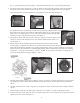
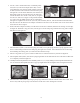
1. Inspect the clamp ring. If clamp ring requires replacement, it is recommended to remove the plastic foot (item 15)
rst. NOTE: 100/112 frame B5 adapters do not use the foot. See gures 32 and 33. Remove the four (4) M6 bolts
(items 28 and 28A).
Figure 32
Figure 33
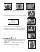
2. Remove the ve (5) M8 bolts, lock washers and at washers (items 34, 33, and 32) from the clamp ring (item
12B). See gure 34. Remove the clamp ring from the motor adapter. There is a snug t between the clamp ring
and motor adapter due to the vapor protection o-ring (item 12C). Carefully pull the two parts apart. See gure 35.
Figure 34 Figure 35
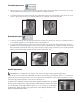
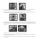
3. Inspect the motor adapter o-ring (item 12C). Replace if damaged. If it is re-
usable, lubricate it with a chemically compatible lubricant. See gure 36.
Figure 36
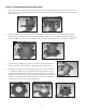
4. Install the new clamp ring. Place the clamp ring on a at surface. See gure
37. Align the bolt holes (ve motor adapter and two foot bolt holes) on the
clamp ring with the bolt holes on the motor adapter. Push the motor adapter
straight down onto the clamp ring to seat the o-ring. See gure 38. Install ve
M8 bolts, lock washers and at washers (items 34, 33 and 32) and tighten in a
star pattern to 130 in-lbs. (14.7 N-m). See gure 39.
Figure 37 Figure 38
Figure 39