SP22 Series Self-Priming Pumps Assembly, Installation and Operation Manual Literature ID No.
TABLE OF CONTENTS Important Notice. . .. . .. . .. . .. . .. . .. . .. . .. . .. . .. . .. . .. . .. . .. . .. . .. . .. . .. . .. . .. . .. . .. . .. . .. . .. . .. . .. . .. . .. . .. 3 Chemical Reaction Disclaimer. . .. . .. . .. . .. . .. . .. . .. . .. . .. . .. . .. . .. . .. . .. . .. . .. . .. . .. . .. . .. . .. . .. . .. . .. . .. . .. 3 Safety Precautions. . .. . .. . .. . .. . .. . .. . .. . .. . .. . .. . .. . .. . .. . .. . .. . .. . .. . .. . .. . .. . .. . .. . .. . .. . .. . .. . .. . .. .
IMPORTANT NOTICE U.S. Export Administration Regulations, pursuant to ECCN 2B350, prohibit the export or reexport to certain enumerated countries of sealless centrifugal pumps in which all wetted materials are constructed from fluoropolymers without first applying for and obtaining a license from the U.S. Bureau of Industry and Security (BIS). This affects all Finish Thompson magnetic-drive pumps constructed from PVDF or lined with ETFE. Please contact the BIS (www.bis.doc.
CAUTION: Never start or operate with a closed suction valve. WARNING: Operation without priming or against a closed discharge valve can result in high temperatures that can result in injury or damage to pump components. CAUTION: Always provide adequate NPSHa (net positive suction head available). It is recommended to provide at least 2 feet (61 cm) above the NPSHr (net positive suction head required).
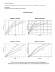
• Priming Liquid Volume Initial filling (or refilling after maintenance) of the pump housing requires (2 1/2) US gallons (9.5 liters) of liquid. • Priming Time Priming time varies with the impeller diameter and speed.
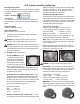
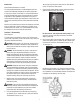
SP22 Assembly, Installation and Operation Unpacking and Inspection towards the motor face. Align (4) holes in the adapter with the holes in the motor face. Install (4) bolts, lock washers and flat washers (items 24, 25, 26) through the motor adapter into the motor face. See figure 1. Unpack the pump and examine for any signs of shipping damage. If damage is detected, save the packaging and notify the carrier immediately.
NOTE: The clearance between the motor adapter and drive magnet is tight (about .010”/.254 mm). • Total suction lift including pipe friction loss and corrections for specific gravity must not exceed 25 feet (7.6 meters). Contact FTI for pumps installed where the elevation exceeds 1,000 feet (305 meters). 5. Install the pump end on the motor/drive magnet assembly. For 182, 184, 213 and 215TC motor frame pumps, install the o-ring (item12B) in the groove in the motor adapter (motor end).
CAUTION: Do not operate the pump to check rotation until the pump is full of liquid. strainer must be periodically cleaned to prevent restriction. Strainer hole size should be 1/8” (1.6 mm) with the amount of open area equal to or greater than 2 times the suction pipe diameter. Check all electrical connections with the wiring diagram on the motor. Make sure the voltage, frequency, phase and amp draw comply with the supply circuit.
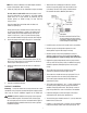
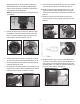
Maintenance 20) securing the pump to the motor. Use 3/8” Allen wrench or 3/8” hex socket on universal joint. Recommended maintenance schedule 3. Firmly grab the motor adapter and pull straight up to disengage the motor and pump. See figure 10. The recommended maintenance schedule depends upon the nature of the fluid being pumped and the specific application.
Applying equal pressure, gently pry both screwdrivers in upward motion away from the table (to avoid damaging sealing surface). See figure 12A. Housing is tight due to oring seal on the internal “gooseneck”. 9. Pull the inner volute straight off. Be careful since the impeller shaft may come out with the inner volute. See figure 17. 10. Remove impeller/inner drive assembly (items 7A, 7, 8, 8A). Inspect for signs of rubbing, damage and wear. See figure 18.
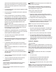
Impeller Bushing 13. Remove the o-ring (item 10) from the barrier and inspect for chemical attack, swelling, brittleness, cuts, etc. Removal 14. Visually inspect the outer drive (item 13) for rubbing, damage, corrosion or loose magnets. 1. To remove the bushing, place the impeller/inner drive assembly (items 7, 7A, 8 & 8A) with the impeller facing up in an arbor press. If necessary support the bottom of the assembly with blocks to allow the bushing to fall out. Insert a 1” (25.
evenly until the prongs snap onto the surface of the inner volute. See figure 29. WARNING: Magnetic force hazard. Keep fingers away from mating surfaces. 4. Install barrier, inner volute, impeller/inner drive and impeller shaft assembly into the motor adapter (item 12). Line up the center of the inner volute bottom port with the center of the motor adapter foot. See Figure 30.
SP22 PART NUMBER EXPLANATION NOTE: Pump end includes wetted components, drive magnet and motor adapter. The wet end includes wetted components only. Part Number Explanation The base model number contains standard components. Where standard components are not suitable, add the alternative component code letter after the base model number to substitute components.
SP22 PARTS DIAGRAM 9 7 2 2A 6 3 4 6A 8 10 11 8A 7A 5 1 6B 16 25 13 17 18 19 15 2A 2 26 24 20 14A 12 13B 13A 22 21 12B 12A 14 23 14
SP22 Spare Parts List Item Qty 1 1 2 2 2A 2 3 1 4 1 5 1 6 1 Description Housing NPT threads BSP threads Fiberglass flanges 2" x 2" Fiberglass flanges 3" x 2" Steel flanges 2" x 2" Unions Fill/Drain Plug Fill/Drain Plug O-Ring FKM EPDM Discharge O-ring (BSP Housings Only) FKM EPDM Inner Volute O-Ring FKM EPDM Separator Plate Polypropylene PVDF 106437 106437-2 106750 107115-2 106750-2 106749 106437-1 106437-3 106750-1 107115-3 106750-3 106749-1 106143 106143-1 106155 106154 105083 105084
SP22 Spare Parts - continued Item Qty 6A 1 6B 1 7 1 7A 1 8 1 8A 1 9 1 10 1 11 1 12 1 12A 1 12B 1 13 13A 1 1 Description Polypropylene Volute / Barrier Seal - 16-1/8” length FKM EPDM Volute / Barrier Seal - 8” length FKM EPDM Impeller Assembly with Thrust Ring See SP22 Impeller Assemblies Table SP22 Closed Impeller Thrust Ring Only Fluorosint SiC Impeller Drive Assembly With carbon bushing With PTFE bushing With ceramic bushing With silicon carbide bushing Impeller Bushing On
SP22 Spare Parts - continued Item Qty 13B 2 14 1 14A 1 Description Polypropylene Set Screws NEMA frames only Motor Adapter Flange 213/215TC 90 B14 90 B5 100/112 B14 & 143/145TC 100/112 B5 132 B14 132 B5 Motor Adapter Flange O-Ring (NEMA 213/215 Frame Motors Only) Buna EPDM FKM PVDF J101084 106775 106781 106780 106777 106776 106779 106778 106775-1 106781-1 106780-1 106777-1 106776-1 106779-1 106778-1 108165 108166 108167 HARDWARE - ALL SP22 MODELS Item Qty 15 10 16 10 17 10 18 4 19
SP22 Impeller Assemblies Thrust Impeller Ring Material PTFE SiC Polypro PVDF Polypro PVDF SiC #1A #1B #1C #2 #2A #2B #2C #3 #3A 7.00" 6.88" 6.75" 6.63" 6.50" 6.38" 6.25" 6.13" 6.00" 5.
Section VI - Troubleshooting • General Notes: • • Primes Slowly • Mismatch of inner volute and impeller diameter • Suction pipe diameter too large (larger than 3 inches) • Closed discharge valve (valve should be open) • Inner volute o-ring chemically attacked, cut, brittle, etc. • • • Cold water will contain dissolved air. Under high lift applications, the air can come out of solution blocking suction passages. This can lead to lack of priming, slow priming or low flow rates.