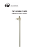
TBP SERIES PUMPS OPERATION & PARTS MANUAL
EU Declaration of Conformity Finish Thompson Inc. hereby declares that the following machine(s) fully comply with the applicable health and safety requirements as specified be the EC Directives listed. The product may not be taken into service until it has been established that the drive motor for the Drum and Container Pump complies with the provisions of all relevant EC Directives.
Introduction This manual pertains to the TBP Series drum pumps. Finish Thompson Inc. thanks you for choosing our products. We believe the use of our products will be fully satisfactory. When properly installed and operated, your Finish Thompson motor and pump will provide long, trouble-free service; therefore, please read this manual carefully before carrying out any operations on the pump/motor unit. Any use other than that described herein is considered incorrect; and, consequently, Finish Thompson Inc.
Warranty, General Terms & Conditions 1. The following terms and conditions apply to the sale of machinery, components and related services and products, of Finish Thompson Inc. (hereinafter “the products”) 2. Finish Thompson Inc. (the manufacturer) warrants only that: a) its products are free of defects in material, design and workmanship at the time of original purchase; b) its products will function in accordance with Finish Thompson Inc. operation manuals; Finish Thompson Inc.
Safety 1. Introduction This manual contains all the information needed for the correct installation, use and maintenance of your new Finish Thompson pump. It should be read and understood by all the personnel involved in installation, operating and servicing of the pump before it is started. 2. Operator Qualification and Training The personnel in charge of the installation, the operation, and the maintenance of the pump must be qualified and able to perform the operations described in this manual.
PUMP SPECIFICATIONS MODEL TBP Outer Tube Diameter 1.66” (4.2 cm) Discharge Thread 1” hose barb Max. Specific Gravity 1.4 Max. Viscosity 200 cP 35°F Min. to 150°F Max. Min./ Max. Fluid Temperature (1.6°C Min. to 66°C Max.
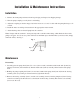
Installation & Maintenance Instructions Installation 1. Remove the drum pump and motor from its packaging and inspect for shipping damage. 2. Turn the pump coupling to verify there is no binding. 3. Adjust the coupling so that the empty slots in the insert are at 3 and 9 o’clock with the pump discharge at 12 o’clock. 4. Install the motor according to instructions in the appropriate motor manual. 5. Attach discharge hose and install pump into the container.
Inspection 1. Visually inspect the compressor (item 11), and the 3 center bearings (item 9) for wear or damage. Replace as needed. 2. Inspect the bearing assembly (item 3) for rust, corrosion, or tightness. Replace as needed. 3. Inspect the pump shaft in the seal area for wear and replace as needed. Reassembly 1. Install the intake tube (item 6) into the pump head (item 5) by threading it counterclockwise (left hand threads). 2.
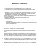
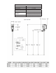
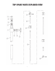
TBP SPARE PARTS EXPLODED VIEW 7
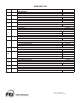
SPARE PARTS LIST ITEM QTY 1 1 2 1 3* 1 4* 1 5 1 6 1 7 1 8 1 9 2 10 1 11 1 12 1 13 1 14 1 DESCRIPTION PART NUMBER COUPLING INSERT J100014 COUPLING HALF J100012 BEARING ASSEMBLY W/ ROLL PIN SEAL ASSEMBLY PTFE PUMP HEAD PURE PVDF INTAKE TUBE ASSEMBLY 27” PURE POLYPROPYLENE 40” PURE POLYPROPYLENE 48” PURE POLYPROPYLENE IMPELLER ASSEMBLY PTFE WITH ALLOY 625 PIN SPACER SET 27” PURE POLYPROPYLENE 40” PURE POLYPROPYLENE 48” PURE POLYPROPYLENE CENTER BEARING PTFE SHAFT 27” ALLOY 625 4