TM SERIES MIXER TMS OPERATION & PARTS MANUAL
EU Declaration of Conformity Finish Thompson Inc. hereby declares that the following machine(s) fully comply with the applicable health and safety requirements as specified be the EC Directives listed. The product may not be taken into service until it has been established that the drive motor for the Drum and Container Pump complies with the provisions of all relevant EC Directives.
Introduction This manual pertains to the TM Series stainless steel drum mixer. Finish Thompson Inc. thanks you for choosing our products. We believe the use of our products will be fully satisfactory. When properly installed and operated, your Finish Thompson motor and pump will provide long, trouble-free service; therefore, please read this manual carefully before carrying out any operations on the pump/motor unit.
Warranty, General Terms & Conditions 1. The following terms and conditions apply to the sale of machinery, components and related services and products, of Finish Thompson Inc. (hereinafter “the products”) 2. Finish Thompson Inc. (the manufacturer) warrants only that: a) its products are free of defects in material, design and workmanship at the time of original purchase; b) c) its products will function in accordance with Finish Thompson Inc. operation manuals; Finish Thompson Inc.
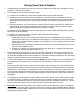
Safety 1. Introduction This manual contains all the information needed for the correct installation, use and maintenance of your new Finish Thompson pump. It should be read and understood by all the personnel involved in installation, operating and servicing of the pump before it is started. 2. Operator Qualification and Training The personnel in charge of the installation, the operation, and the maintenance of the pump must be qualified and able to perform the operations described in this manual.
PUMP SPECIFICATIONS MODEL TMS Outer Tube Diameter 2” (5.1 cm) Max. Viscosity 1000 cP -20°F Min. to 200°F Max. Min./ Max. Fluid Temperature (-29°C Min. to 93°C Max.
Installation & Maintenance Instructions Installation 1. Remove the mixer and motor from the packaging and inspect for shipping damage. 2. Turn the shaft coupling and the motor coupling to verify there is no binding. 3. Adjust the mixer coupling so that the empty slots in the insert are at 3 and 9 o’clock. 4. Install the motor according to instructions in the appropriate motor manual. 5. Install into the container. Maintenance Disassembly 1.
Reassembly 1. Insert the center bearing (item 10) up through the bottom of the tube and match up the setscrew hole in the tube and the center bearing. Install the setscrew. 2. Insert the shaft assembly up through the bottom, and through the center bearing until the shaft sticks out above the mixer tube top. 3. Warm up the seal assembly (item 4) prior to installation by using a heat lamp or socking them in hot water. This will aid in the ease of proper seal installation.
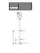
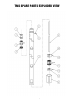
TMS SPARE PARTS EXPLODED VIEW 6
SPARE PARTS LIST ITEM QTY 1 1 2 1 3* 1 4* 1 5 1 6 1 7 1 8 1 9* 1 10 1 11 1 12* 1 13* 2 DESCRIPTION PART NUMBER COUPLING INSERT J100014 COUPLING HALF J100013 BEARING ASSEMBLY W/ ROLL PIN SEAL ASSEMBLY TFE LOCK WASHER #8 BRASS SCREW #8-32 X 1/4 BRASS PAN HEAD M/S TUBE ASSEMBLY 40” - 316 STAINLESS STEEL SLEEVE 316 STAINLESS STEEL SHAFT 316 STAINLESS STEEL CENTER BEARING PTFE TURBINE ASSEMBLY WITH STAINLESS STEEL PIN BOTTOM BEARING PTFE SET SCREW #8-32 X 3/8 STAINLESS STEEL A10167