ME T A L A N S I TM M A G LI N E D I M E N S I O N A L M A G OPERATIONAL MANUAL Use this manual for pump serial numbers up to 125040 Record your Model and Serial Number here.
Table of Contents Warranty Statement................................................................................................................................. 3 Safety Precautions................................................................................................................................... 3 ULTRAChem Features.............................................................................................................................. 4 ULTRAChem Capabilities.......................
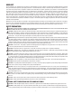
WARRANTY Finish Thompson, Inc (manufacturer) warrants this pump product to be free of defects in materials and workmanship for a period of two years from date of purchase by original purchaser. If a warranted defect, which is determined by manufacturer’s inspection, occurs within this period, it will be repaired or replaced at the manufacturer’s option, provided (1) the product is submitted with proof of purchase date and (2) transportation charges are prepaid to the manufacturer.
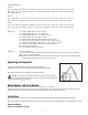
ULTRAChem Features The Finish Thompson ULTRAChem is a sealless, magnetically driven, ANSI dimensional, ETFE lined, chemical pump. It has been specifically designed for corrosive chemical applications in a wide range of industrial services. The ULTRAChem features a closed impeller, suction straightening vanes, balanced axial thrust with a rear sealing ring, balance holes and balanced radial thrust due to the modified concentric volute shape.
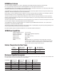
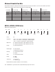
Minimum Allowable Flow Rate Do not allow the flow rate to drop below the minimum flow rate listed in the chart below. Use the first six characters (five for the UC326) from the model number listed on label found on the motor adapter. Pump Model Minimum GPM @ 3500 rpm (60 Hz) UC1516 UC1516 UC1518 UC1518 UC326 UC326 Minimum m3/hr @ 2900 rpm (50 Hz) 5 5 5 5 5 5 Minimum GPM @ 1750 rpm (60 Hz) 1.1 1.1 1.1 1.1 1.1 1.1 Minimum m3/hr @ 1450 rpm (50 Hz) 3 3 3 3 3 3 .75 .75 .75 .75 .75 .
UC Impeller Diameters: UC1516 = 637 (6 3/8”); 625 (6 1/4”); 612 (6 1/8”); 600 (6”); 587 (5 7/8”); 575 (5 3/4”); 562 (5 5/8”); 550 (5 1/2”); 537 (5 3/8”); 525 (5 1/4”); 512 (5 1/8”); 500 (5”); 487 (4 7/8”); 475 (4 3/4”); 462 (4 5/8”); 450 (4 1/2”); 437 (4 3/8”); 425 (4 1/4”); 412 (4 1/8”); 400 (4”) UC1518 = 812 (8 1/8”); 800 (8”); 787 (7 7/8”); 775 (7 3/4”); 762 (7 5/8”); 750 (7 1/2”); 737 (7 3/8”); 725 (7 1/4”); 712 (7 1/8”); 700 (7”); 687 (6 7/8”); 675 (6 3/4”); 662 (6 5/8”); 650 (6 1/2”); 637 (6 3/8”); 62
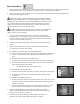
Pumps without Motors: 1. Prepare to install the motor on the pump. Carefully place the motor and pump end on a suitable, level work surface (a nonmagnetic surface is preferred). Make sure the work surface is free of metal chips or particles. 2. Using a 9/16” open-end wrench, remove the (4) 3/8” hex head cap screws (item 16) from the motor adapter flange (item 10) and motor adapter (item 9). Magnetic Force Hazard. This pump should only be disassembled and assembled using the recommended procedures.
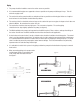
9. Slowly and evenly turn the jackscrews counterclockwise to allow the wet end to slowly slide into the motor adapter. When the jackscrews are fully retracted, lift the wet end slightly and slide it onto the motor adapter’s locating flange. 10. Bolt the wet end to the motor adapter by reinstalling the (4) ½” hex head cap screws (item 15) and torque evenly to 75 ft-lbs (102 N-m). Foundation 1. 2.
Piping 1. The pump should be installed as near to the suction source as possible. 2. It is recommended that pipes are supported as close as possible to the pump and all flanges line up. This will minimize any pipe strain. 3. The suction side of the pump should be as straight and short as possible to minimize pipe friction or a length at least ten times the inlet diameter should follow any elbows. 4.
Motor/Electrical Install the motor according to NEC requirements and local electrical codes. The motor should have overload protection. The use of a power monitor is highly recommended. Note: All ATEX certified pumps must use a power monitor. 1. The motor must be installed with flexible conduit in order to allow a minimum of 6” of motor movement so that the pump can be disassembled. 2. Check all electrical connections with the wiring diagram on the motor.
CAUTION: Do not run the pump dry. This could damage the pump. The fluid being transferred by the pump lubricates the pump. Even short periods of running the pump dry could damage the pump. It is recommended that a run dry protection device be used. CAUTION: Do not dead head the pump. Running the pump at zero flow will cause any liquid inside the pump to elevate rapidly in temperature. This will continue until the boiling point of the liquid is reached.
1. Stop the pump, lock out the motor starter, close all the valves that are connected to the pump, and drain/decontaminate the pump. The ULTRAChem is supplied with a casing drain to help drain and decontaminate the pump. If the drain flange has been removed to drain/decontaminate the pump, reinstall the flange (item 11) and use a new gasket (item 11A). Torque the two flange bolts (¼”) (item 11B) to 20 ft-lbs (27.1 N-m). 2. Allow the pump to reach ambient temperatures prior to performing maintenance.
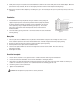
Disassembly 1. Using a 9/16” socket, remove the (4) 3/8” hex head cap screws (item 16) between the motor adapter (item 9) and motor flange (item 10). Remove the motor adapter by slipping it over the drive hub (item 8). 2. For pumps with 145TC, 184TC, 215TC & 256TC NEMA motors - loosen both set screws and remove the outer drive. For pumps with 90, 100/112 and 132 frame motors - remove the bolt and washers in the end of the motor shaft and remove the drive.
6. Check the impeller drive assembly (item 4) for cracks or grooves larger than .02 inch. If a fluid comes in direct contact with the magnets, the magnets may swell, cause rubbing, and damage the barrier assembly (item 6). 7. Inspect the barrier assembly for signs of abrasion. Replace the barrier assembly if there are grooves or scratches that are deeper than .04 inch. Replacing Wear Components Use the following procedures to replace any wear components that are excessively worn, cracked or broken.
Rear Sealing Ring - For Pumps with Serial Numbers 119145-I13 & Above The rear sealing ring (item 4C) is located in the rear bore of the barrier assembly (item 6). Removal 1. Place barrier (item 6) on a table with open side facing up. 2. Remove rear sealing ring by cutting it with a #18 straight edge X-Acto knife or similar blade & gently cut through the ring. Once cut, simply spread open and remove the ring from the barrier inner shaft boss. (See figure 18i.) figure 18i Replacement 1.
Impeller Assembly Removal and Replacement The impeller assembly can be replaced as required to change the impeller diameter or replace damaged or worn vanes. Removal 1. Holding the impeller and impeller drive assembly (items 3,3A, 4,4A, 4B, 4C) by hand, place a 3/8-inch diameter rod (or a 3/8” ratchet extension) through the perforations in the bore of the impeller drive assembly (item 4). figure 19 2.
Power End Reassembly See section Assembly of Pumps without Motors, steps 1-7: Pump End Reassembly 1. Take the pump casing (item 1) and lay it suction side down on a clean flat sur- face (see figure 23). figure 23 2. Insert the shaft’s (item 5) rounded end into the round hole in the shaft support (item 2) in the casing (see figure 24). 3. Carefully place the impeller and impeller drive assembly (items 3A, 3,4,4A, 4B, 4C) on the pump shaft (see figure 25).
TROUBLESHOOTING CHEMICAL REACTION DISCLAIMER NO OR INSUFFICIENT DISCHARGE • Air leaks in suction piping. • Pump not primed. • Discharge head higher than anticipated. • Closed valve. • Viscosity or specific gravity too high (magnets uncoupled). • Suction lift too high or insufficient NPSH. • Clogged suction line or impeller vanes. • Motor rotation incorrect (correct rotation when viewed from the fan end is clockwise). INSUFFICIENT PRESSURE • Air or gas in liquid. • Impeller diameter too small.
UC EXPLODED VIEW PARTS DIAGRAM 13 7 6 10 12 16 14 5 15 9 4 8C , 8A 8B 4A 4B 17 18 4A 19 3 20 4C 3A 2A 2 1 11A 11 11B 19
UC Spare Parts Item Qty Description Part Number Casing (ETFE-lined Cast Ductile Iron) UC1516 A103145 1 1 UC1518 A103146 UC326 A103147 Front Shaft Support Only 2 1 2A sold separately M102206 Silicon Carbide Front Thrust Ring Only For use with all models except UC1516 w/ SiC impeller thrust ring J103659 2A 1 For use w/ UC1516 pumps w/ silicon carbide impeller thrust ring option only J104174 Impeller Assembly 3 1 With Fluorosint thrust ring See charts on pg.
Item 7 Qty 1 8 1 8A 2 9 1 10 1 11 1 11A 1 11B 2 12 1 13 12 14 3 15 4 16 4 Description Part Number Clamp Ring M102184 Outer Drive Assembly w/ Set Screw 143-145TC “A” magnet 182-184TC “A” magnet 213-215TC “A” magnet 182-184TC “B” magnet 213-215TC “B” magnet 254-256TC “B” magnet 90 frame “A” magnet 110/112 frame “A” magnets 132 frame “A” magnets 132 frame “B” magnets 160 frame “B” magnets Set Screw Outer drive Motor Adapter "A" magnet "A" magnet w/ non-sparking ring (ATEX) "B" magne
Item Qty 17 1 18 1 19 1 20 1 Description Retaining Ring 145TC 182TC 215TC 256TC 90 frame 100/112 frame 132 frame 160 frame Drive Retaining Flat Washer 90 frame 100/112 frame 132 frame A 132 Frame B Drive Retaining Lock Washer 90 frame 100/112 frame 132 frame B Drive Hub Bolt 90 frame 100/112 frame 132 frame A 132 frame B 160 frame Part Number 105709 105710 106454 106718 105712 105710 106468 106714 105722 J101360 106716 106509 J102282 105757 106503 105770 105757 106717 106507 106715 22
UC1516 Impeller Part Numbers with Fluorosint® Thrust Ring Imp. Dia. 6 3/8” 6 ¼” 6 1/8” 6” 5 7/8” 5 ¾” 5 5/8” 5 ½” 5 3/8” 5 ¼” 5 1/8” 5” 4 7/8” 4 ¾” 4 5/8” 4 ½” 4 3/8” 4 ¼” 4 1/8” 4” Part Number A103166-1 A103166-2 A103166-3 A103166-4 A103166-5 A103166-6 A103166-7 A103166-8 A103166-9 A103166-10 A103166-11 A103166-12 A103166-13 A103166-14 A103166-15 A103166-16 A103166-17 A103166-18 A103166-19 A103166-20 UC1518 Impeller Part Numbers with SiC Thrust Ring and PTFE Encapsulated O-ring Imp. Dia.