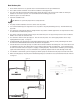
ME T A L A N S I TM M A G LI N E D I M E N S I O N A L M A G OPERATIONAL MANUAL Record your Model and Serial Number here.
Table of Contents Warranty Statement................................................................................................................................. 3 Safety Precautions................................................................................................................................... 3 ULTRAChem Features.............................................................................................................................. 4 ULTRAChem Capabilities.......................
WARRANTY Finish Thompson, Inc (manufacturer) warrants this pump product to be free of defects in materials and workmanship for a period of two years from date of purchase by original purchaser. If a warranted defect, which is determined by manufacturer’s inspection, occurs within this period, it will be repaired or replaced at the manufacturer’s option, provided (1) the product is submitted with proof of purchase date and (2) transportation charges are prepaid to the manufacturer.
ULTRAChem Features The Finish Thompson ULTRAChem is a sealless, magnetically driven, ANSI dimensional, ETFE lined, chemical pump. It has been specifically designed for corrosive chemical applications in a wide range of industrial services. The ULTRAChem features a closed impeller, suction straightening vanes, balanced axial thrust with a rear sealing ring, balance holes and balanced radial thrust due to the modified concentric volute shape.
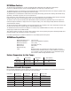
Minimum Allowable Flow Rate Do not allow the flow rate to drop below the minimum flow rate listed in the chart below. Use the first five or six characters from the model number listed on label found on the motor adapter. Pump Model Minimum GPM @ 3500 rpm (60 Hz) UC1516 UC1518 UC326 Minimum m3/hr @ 2900 rpm (50 Hz) 5 5 5 Minimum GPM @ 1750 rpm (60 Hz) 1.1 1.1 1.1 Minimum m3/hr @ 1450 rpm (50 Hz) 3 3 3 .75 .75 .
UC Impeller Diameters: UC1516 = 637 (6 3/8”); 625 (6 1/4”); 612 (6 1/8”); 600 (6”); 587 (5 7/8”); 575 (5 3/4”); 562 (5 5/8”); 550 (5 1/2”); 537 (5 3/8”); 525 (5 1/4”); 512 (5 1/8”); 500 (5”); 487 (4 7/8”); 475 (4 3/4”); 462 (4 5/8”); 450 (4 1/2”); 437 (4 3/8”); 425 (4 1/4”); 412 (4 1/8”); 400 (4”) UC1518 = 812 (8 1/8”); 800 (8”); 787 (7 7/8”); 775 (7 3/4”); 762 (7 5/8”); 750 (7 1/2”); 737 (7 3/8”); 725 (7 1/4”); 712 (7 1/8”); 700 (7”); 687 (6 7/8”); 675 (6 3/4”); 662 (6 5/8”); 650 (6 1/2”); 637 (6 3/8”); 62
Pumps without Motors: 1. Carefully place the motor on a suitable, level work surface (a nonmagnetic surface is preferred). Make sure the work surface is free of metal chips or particles. 2. Coat the motor shaft with anti-seize paste. Magnetic Force Hazard. This pump should only be disassembled and assembled using the recommended procedures. The magnetic attraction is powerful enough to rapidly pull the motor end and the wet end together.
9. Slide the motor adapter over the shaft adapter and secure the motor face using hex head bolts (Items 16 & 16A) and lock washers. See figure 3. Torque the hex head bolts to the following values: A. B. C. D. 145TC 3/8-16 bolt: 75 ft-lbs 182/184TC, 213/215TC, 254/256TC 1/2-13 bolt: 75 ft-lbs IEC 90 & 100/112 M8-1.25 bolt: 120 in-lbs IEC 132 M12-1.
Grout the base plate 1. Ensure that the area that is to be grouted is clean. Follow instructions from the grout manufacturer. 2. Erect a dam around the foundation. Insure that the foundation is thoroughly wetted. 3. Pour grout in the dam and completely fill under and around the base plate to the level of the dam. Make sure that any air bubbles are removed as it is poured. It is recommended that non-shrinking grout be used. 4. Permit the grout to set at least 48 hours. 5.
Motor/Electrical Install the motor according to NEC requirements and local electrical codes. The motor should have overload protection. The use of a power monitor is highly recommended. Note: All ATEX certified pumps must use a power monitor. 1. The motor must be installed with flexible conduit in order to allow a minimum of 6” of motor movement so that the pump can be disassembled. 2. Check all electrical connections with the wiring diagram on the motor.
Shutdown Use the following procedures to shut the pump down. 1. Slowly close the discharge valve . 2. Shut off the motor. 3. Close the suction valve. Disassembly/Reassembly Disassembly Pump End WARNING: Rotating Parts. This pump has components that rotate while in operation. Follow local safety standards for locking out the motor from the power supply during maintenance or service. WARNING: Chemical Hazard. This pump is used for transferring many types of potentially dangerous chemicals.
8. Remove the impeller assembly and the shaft from the casing. See figure 13. CAUTION: The shaft and impeller can be damaged if dropped. Disassembly Power End (motor side) WARNING: This pump should only be disassembled and assembled using the recommended procedures. The magnetic attraction is powerful enough to rapidly pull the motor end and the wet end together. ALWAYS use the jackscrews (item 14) to assemble/disassemble the pump.
3. Check for signs of deformation or melting in the shaft support (item 2) and the barrier liner where the pump shaft is positioned. Dry running the pump during its initial start-up or operation can cause heat-related damage to these components. 4. Inspect the casing liner. It is important that there are no abrasions or cuts deeper than .04 inch in the lining. These cracks may occur if the lining is corroded or abraded. Liner damage can usually be detected visually.
Rear Sealing Ring The rear sealing ring (item 4C) is located in the rear bore of the barrier assembly (item 6). Removal 1. Place barrier (item 6) on a table with open side facing up. 2. Remove rear sealing ring by cutting it with a #18 straight edge X-Acto knife or similar blade & gently cut through the ring. Once cut, simply spread open and remove the ring from the barrier inner shaft boss. See figure 22. Replacement figure 22 1.
Impeller Bushings Removal 1. Remove the impeller (item 3, 3A) according to the steps listed in the section Impeller Assembly, Removal. 2. Place the impeller drive assembly (items 4,4A, 4B, 4C) on an arbor press with the front of the impeller drive facing down. 3. Insert a 1” diameter arbor into the bore of the impeller drive assembly. See figure 30. 4. Press on face of rear impeller bushing until (2) bushings (item 4A) and (1) spacer (item 4B) have been removed. Check for excessive wear.
6. Place the rounded edge of the clamp ring (Item 7) over the barrier assembly and position on the rear face of the casing. Make sure to align the flat on the bottom of the clamp ring with the flat on the bottom of the casing. Attach the clamp ring with (12) 3/8” socket head cap screws (item 13). Tighten evenly around circumference. Torque the screws to 35 ft-lbs (47 N-m) unlubricated. See figure 37. 7.
TROUBLESHOOTING CHEMICAL REACTION DISCLAIMER NO OR INSUFFICIENT DISCHARGE • Air leaks in suction piping. • Pump not primed. • Discharge head higher than anticipated. • Closed valve. • Viscosity or specific gravity too high (magnets uncoupled). • Suction lift too high or insufficient NPSH. • Clogged suction line or impeller vanes. • Motor rotation incorrect (correct rotation when viewed from the fan end is clockwise). INSUFFICIENT PRESSURE • Air or gas in liquid. • Impeller diameter too small.
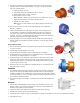
UC EXPLODED VIEW PARTS PARTS DIAGRAM UC EXPLODED VIEW DIAGRAM 4C 4 3A 4B 2A 2 1 3 5 27 4A 11 11A 19 8A 11B 8B 21 22 17 18 20 13 23 7 6 24 26 8 12 9 16 16A 15 24 25 14 18 10
UC Spare Parts Item Qty 1 1 2 1 2A 1 3 1 3A 1 3B 1 4 1 4A 2 4B 1 4C 1 5 1 6 1 7 1 Description Part Number Casing - ETFE-lined Cast Ductile Iron UC1516 A103145 UC1518 A103146 UC326 A103147 Front Shaft Support Only (2A sold separately) ETFE M102206 Front Thrust Ring Only - Silicon Carbide All models except UC1516 w/ SiC impeller thrust ring option J103659 UC1516 pumps w/ silicon carbide impeller thrust ring option only J104174 Impeller Assembly ETFE See charts on pg.
Item Qty 8 1 8A 1 8B 1 9 1 10 1 11 1 11A 1 12 1 24 2 Description Outer Drive Assembly w/ Set Screw - Painted Ductile Iron/Steel 143-145TC “A” magnet 182-184TC “A” magnet 213-215TC “A” magnet 182-184TC “B” magnet 213-215TC “B” magnet 254-256TC “B” magnet IEC 90 B14 “A” magnet IEC 110/112 B14 “A” magnets IEC 132 B5 “A” magnets IEC 132 B5 “B” magnets IEC 160 B5 “B” magnets Outer Drive Magnet Hub - Painted Ductile Iron “A” magnet “B” magnet Shaft Adatper - Painted Steel (Includes Retaining R
Item Qty 25 1 26 1 Description Motor End Vapor Protection O-ring - Buna NEMA 143-145TC NEMA 182-184TC, 213-215TC, 254-256TC IEC 90 B14 IEC 100-112 B14 IEC 132 B5 IEC 160 B5 Motor Adapter Flange Vapor Protection O-ring - Buna IEC 160 B5 only Part Number 106549 108165 106548 108588 108589 108165 108594 Hardware - All Models 11B 2 13 12 14 2 15 4 16 16A 4 4 17 1 18 1 19 1 Drain Cap Hex Head Cap Screw - Stainless Steel 1/4-20 x 3/4 Casing Hex Head Cap Screw - Stainless Steel 3/8-16 x 1
20 1 21 2 22 4 23 2 27 2 Shaft Bolt - Stainless Steel (IEC Motors Only) IEC 90 B14, IEC 100-112 B14 - M8-1.25 x 25mm hex head cap screw IEC 100-112 B14 - M10-1.5 x 35mm fillister head cap screw IEC 132 B5 - M12-1.75 x 30mm hex head cap screw IEC 160 B5 - M16-2 x 35mm hex head cap screw Shaft Adapter Hex Nut - Stainless Steel M8 Shaft Adapter Lock Washer - Stainless Steel 5/16” Shaft Adapter Hex Head Cap Screw - Stainless Steel M8-1.
UC1516 Impeller Part Numbers with Fluorosint® Thrust Ring Imp. Dia. 6 3/8” 6 ¼” 6 1/8” 6” 5 7/8” 5 ¾” 5 5/8” 5 ½” 5 3/8” 5 ¼” 5 1/8” 5” 4 7/8” 4 ¾” 4 5/8” 4 ½” 4 3/8” 4 ¼” 4 1/8” 4” Part Number A103166-1 A103166-2 A103166-3 A103166-4 A103166-5 A103166-6 A103166-7 A103166-8 A103166-9 A103166-10 A103166-11 A103166-12 A103166-13 A103166-14 A103166-15 A103166-16 A103166-17 A103166-18 A103166-19 A103166-20 UC326 Impeller Part Numbers with SiC Thrust Ring and PTFE Encapsulated O-ring Imp. Dia.