English DHS40-HG-SCH-2 - Signal Amplifier User & Installation Manual UM-0915 1
Document History Description Revision Date Issued Original 1.0 June 1st, 2015 Update SAR values 2.
About this manual This manual describes installation, commissioning, operation and maintenance of Fiplex DHS40-HG-SCH-2 Signal Amplifier, and Fiplex Control Software (FCS). The first part of the manual describes the Signal Amplifier hardware and the second part describes the software. Hardware and software mentioned in this manual are subjected to continuous development and improvement.
Exposure Statement ATTENTION: This unit has a maximum output power of +40dBm +/- 2dBm, therefore the gain of the antenna should be of 0dBi or less and maintain a minimum separation of 36 cm from all persons to comply with SAR and/or RF field strength limits.
Part 1 HARDWARE 1. Safety Caution! This manual lists a set of rules and warnings to be accomplished when installing, commissioning and operating a DHS40-HG-SCH-2 Signal Amplifier from FIPLEX. Any omission may result in damage and/or injuries to the Amplifier and/or the Amplifier Operators or Users. If an instruction is not clear or you consider is missing, please contact immediately to Fiplex. See www.fiplex.com for contact information.
2. Product Description. The DHS40-HG-SCH-2 Signal Amplifier are single channel amplifiers that operates in the downlink frequency of 851-869MHz for United States. This Signal Amplifiers amplifies the RF signal of a Base Station or Transmitter equipment without the need of a previous amplification (driver, power amplifier). The system receives the BTS or Transmitter signal to be amplified, filters, amplifies and re-radiates through the connected antenna/s.
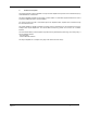
3. Ports 4. Commissioning 1. Connect RF IN and RF OUT. N type female connectors are used in the Signal Amplifier. 2. Once RF ports of the Signal Amplifier are properly loaded connect the DC port. Electrical installation must provide differential and termo-magnetic breaker elements according to electric safety international regulations. 3. Signal Amplifier chassis must be properly DC grounded. 4. Turn ON DC power. 5.
UM-0915 3. Setup desired operating gain using FCS. 4. Set up squelch settings.
5.
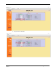
Part 2 SOFTWARE 1. Introduction Fiplex Signal Amplifier can be fully configured and monitored in local and remote mode. Local mode: o USB port with Windows desktop application Remote mode: o Remote Web server In following section, each control mode (configuration / monitoring) are described. 2. Local Software. Desktop application through USB port 2.1.
UM-0915 3. The installer will start to copy the necessary files. 4. After installation has completed, a shortcut in user desktop will appear. 5. Connect USB cable between computer and Signal Amplifier, keeping the Signal Amplifier powered off. Usually, drivers will be automatically installed, but depending on Windows version, screen asking for drivers of new device can appear. Drivers can be found in application folder: C:\Program Files (x86)\FiplexControlSoftware\drivers”.
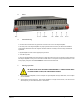
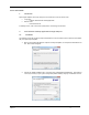
6. Turn on the Signal Amplifier BE SURE THAT RF PORTS ARE PROPERLY LOADED EITHER WITH 50 OHMS DUMMY LOADS, OR RADIATING SYSTEM. 7. Execute the Fiplex Control Software. Next window will appear: User interface controls: UM-0915 Scan Devices Button: refresh the available COM ports and identify Fiplex devices Connection Button: connect / disconnect software from Signal Amplifier List of available devices: below two buttons, is placed a dropdown list that shows all available COM ports.
File menu: contains menus to save Signal Amplifier configuration to a file and load configuration from file to Signal Amplifier. NOTE: if Fiplex Signal Amplifier is not turned on, related COM port will appear as “Unknown device” 8. Click “Scan Devices” Now, the Fiplex Digital Signal Amplifier is shown in the list of available devices, and connection button is enabled. NOTE: Fiplex Signal Amplifier could not appear in list, if COM port number is higher than COM16, depending on Windows version.
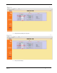
Change COM port number 9. UM-0915 Click “Connect”. Fiplex Control Software window will be automatically maximized, and web browser will show the configuration screen. Application screens are described in the next section due to these application screens and web pages (in webserver remote mode) are the same.
10. Once Signal Amplifier is configured, user can disconnect software using connection button, now labelled “Disconnect”. Initial window will be shown. If Signal Amplifier is disconnected or turned off, while Fiplex Control Software is connected to device, software will go back to initial window. Moreover, if some communication problem occurs while device is monitored, the software will go back to initial state as well.