
Manual

2401B/2402B Circuit Board
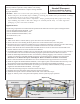
Standoff Placement
Product Installation Drawing
Document 52599 Rev A 4/15/05 ECN 05-205
CAUTION! Make sure to observe all of the following precautions:
• Remove all power (AC and DC) before installing or removing any modules since personal harm or damage
to components may occur if power remains applied.
• Circuit boards contain static-sensitive components. Always ground yourself with a proper wrist strap
before handling any boards so that static charges are removed from the body. Use static suppressive
packaging to protect electronic assemblies.
Supplied Hardware
The following components are included with the replacement kit and must be used to replace existing hardware:
• Four #4-40 Female/Female Standoffs, 1.125"
• Four #4-40 Male/Female Standoffs, 0.750"
• Four #4-40 Male/Female Standoffs, 0.375"
• Six #4-40 Screws, 0.25"
Installation
1. Make certain that AC and DC (battery) power have been removed from the panel.
2. Remove the four screws holding the dress panel to the circuit board and remove the dress panel.
3. Disconnect all power connections including AC wiring, transformer and battery connectors as well as field wiring
from the circuit board. Label, if necessary, to facilitate reconnection to the new circuit board.
4. Remove and discard the four Female/Female standoffs which secure the circuit board to the standoffs in the
backbox and then remove the circuit board from the backbox.
5. If a 4XTM Option Board is installed, remove it from the old circuit board by removing the two screws securing it
to the standoffs on the circuit board and carefully unplug the Option Board from the main circuit board.
6. Install the 4XTM Option Board on the new circuit board by carefully plugging it into connectors J1 and J4 and
securing it to the factory-installed standoffs on the new circuit board with two supplied screws from the kit.
(Remember to cut Resistor R14 if the 4XTM Option Board is installed on the main circuit board).
7. Remove from the backbox and discard the four sets of standoffs used to support the main circuit board.
8. Install the supplied #4-40 Male/Female Standoffs, 0.750" length in place of the standoffs removed in step 7 and
then install the supplied #4-40 Male/Female Standoffs, 0.375" length on the standoffs just installed.
9. Install the new circuit board in the backbox by securing it to the newly installed standoffs (see step 8) with the
supplied #4-40 Female/Female Standoffs, 1.125" length.
10. Connect all field wiring and power connections removed in step 3.
11. Duplicate the switch and jumper settings from the original circuit board.
12. Install the dress panel to the circuit board with the four screws removed in step 2
13. Apply AC and DC power to the panel and completely test the system for proper operation.
The 2401B/2402B replacement circuit board is provided with the
necessary hardware required to safely install it in an existing
panel. Use the supplied hardware to replace existing standoffs
for proper installation.
Step 5
Steps 7 & 8
Steps 2 & 12
Steps 4 & 9
Steps 7 & 8
2401B/2402B Circuit Board
Dress Panel
Backbox