
User guide

Document #51130 Rev. B 5/10/02 P/N 51130:B 1 of 2
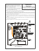
The communicator Dress Panel (required for Canadian
applications) can be installed to prevent accidental contact
with the AC wiring terminals and wiring connected to other
terminals. To install the Dress Panel:
1. As a safety precaution, it is highly recommended that all
power be removed from the main circuit board before
proceeding with installation procedure.
2. Remove and save the four screws and attached washers which are used to secure the four corners of the main
circuit board to the backbox mounting standoffs. Refer to Figure 1.
3. Install and tighten the four standoffs, which were supplied with the Dress panel, in the four corner holes which
were just vacated in step 2. Note that the male threaded end is used to resecure the main circuit board to the
backbox mounting standoffs. Refer to Figure 1.
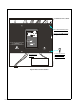
4. Position the four holes in the Dress Panel over the four standoffs installed in step 3. Note that the notched
edge of the Dress Panel must be positioned to the right in order to accommodate the lock mechanism. Refer to
Figure 2.
5. Complete the installation by securing the Dress Panel with the four screws and attached washers which were
removed in step 2. Refer to Figure 2.
6. If all other installation has been completed, reapply power to the main circuit board .
EARTH AC-NEU AC-HOT
CAUTION!
HIG H V O LTAG E
K6
K5
TB4
TB2
PH1
PH2
J1
J2
J8
J7
J3
BATTERY
SUPV.
SYS TRBL
BATT FAULT
COMM.FAIL
AC PWR
RELAY 2
NO NC C
NAC
B+ B-
ZONE 1
B+ B-
ZONE 2
B+ B-
ZONE 4
B+ B-
ZONE 3
B+ A+ A- B-
+12V PWR
+ -
RELAY 1
NO NC C
ALARM
GND
FAULT
J4
TB3
TB1
- +
Figure 1: Mounting Screws
411AULPW.CDR
Remove All Power
(Step 1)
Remove and Retain Four
Mounting Screws From
the Corners
(Step 2)
Mounting
Screw
(Step 2)
Mounting
Screw
(Step 2)
Mounting
Screw
(Step 2)
Install Four Supplied
Standoffs in Place of
Mounting Screws
(Step 3)
Document #51130 Rev. B 05/10/02 ECN 02-255
Communicator
Dress Panel
Product Installation Drawing