
User guide


18 Distributed Audio Panel Manual — P/N 52265:B1 6/8/2010
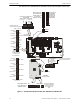
Product Description Specifications
Backup Audio In - TB2, Terminals 1(+) & 2(-) [Out Terminals 3(+) & 4(-)] on Amplifier
Module
Operation: When TB2 is wired between the two amplifiers of a panel, the optional amplifier pro-
vides backup to the standard amplifier. Switch S1 on the backup amplifier must be 'ON' and jump-
ers placed from backup amplifier TB2 Terminal 3 to standard amplifier TB2 Terminal 1 and from
backup amplifier TB2 Terminal 4 to standard amplifier TB2 Terminal 2. Refer to Section “One
Speaker Circuit With Backup” on page 62, for additional information.
Speaker Circuit - TB1 Terminals 3(+) & 4(-) Style Y, 3(+), 4(-), 5(+) & 6(-) Style Z, 1 & 2
Shield (Standby and Alarm Polarity Shown) on Amplifier Module
Power-limited, supervised circuitry
Operation: Circuit can be wired Style Y or Style Z
Normal Operating Voltage: 25 V
RMS
@ 1 amp max. and maximum Load Impedance of 25
(70.7 V
RMS
@ 350 mA max. with maximum Load Impedance of 200operation possible
by plugging optional FC-XRM70 conversion module into P1 of audio amplifier).
Circuit wiring is supervised during standby, alarm and when background music is playing
Output Power: 25 watts (20 watts when background music is employed).
Frequency Range: 800Hz - 2,800Hz
Maximum total capacitance for each ACC-AAM25: 250 µF.
End-of-Line Resistor required for Style Y circuit: 4.75 K, 1 watt (P/N: 75470)
ACC-ZSM Zone Splitter Module and ACC-ZPM Zone Page Module
Power-limited circuitry
Operation: Circuits on ACC-ZSM can be wired as eight Style Y or four Style Z
Normal Operating Voltage for Speaker Circuits: 25 V
RMS
@1 amp Max. and maximum Load
Impedance of 25
(70.0 V
RMS
@ 350 mA max. with maximum Load Impedance of 200operation possible
by plugging optional FC-XRM70 conversion module into P1 of audio amplifier).
Speaker circuit wiring is supervised during standby and alarm. (Note that background music is not
permitted in Zone Splitter configuration since open-circuit fault detection is not possible.)
Output Power: 25 watts total.
Frequency Range: 800Hz - 2,800Hz
Maximum total capacitance for ACC-AAM25: 250 µF. (Note that the total
capacitance for the
ACC-ZSM speaker outputs must not exceed the maximum of 250 µF.)
End-of-Line Resistor required for Style Y (Class B) speaker circuit: 4.75 K, 1 watt (P/N: 75470)
TB1 on ACC-ZPM: ACS (EIA-485) electrically isolated link to FACP provides programmed
speaker control
Master CMD Bus - TB8 Terminals 1(-), 2(+), 3(+) & 4(-) (active polarity shown)
Provides reverse polarity trigger input from ACC-25/50 Series Master Command Bus Output.
Supervised and power-limited circuitry
Normal Operating Voltage: 24 VDC regulated, filtered.
Maximum Voltage: 25.4 VDC
Reverse Polarity Current: 125 mA maximum.
Standby Voltage: -5 VDC. Short Circuit Current: 0.5 mA.
Maximum Load Resistance: 200 ohms.
Wiring connections to Master CMD Bus Circuit: