
User guide

44 Distributed Audio Panel Manual — P/N 52265:B1 6/8/2010
Installation Output Circuits
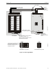
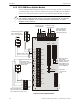
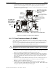
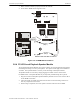
3.6.5 ACC-ZSM Zone Splitter Module
The ACC-ZSM Zone Splitter Module provides connections for four Style Z (Class A) or eight Style
Y (Class B) speaker circuits. Circuits are configured by setting switch SW2 on the ACC-ZSM to
the Class A or Class B position (refer to Section “ACC-ZSM Zone Splitter Module” on page 30).
!
CAUTION: OBSERVE WIRING
FOR CORRECT SUPERVISION IN THE SPLIT AMPLIFIER CONFIGURATION, ACC-ZSM TB2
PINS 1 & 2 MUST CONNECT TO ACC-AAM25 #1 AND ACC-ZSM TB9 PINS 1 & 2 MUST
CONNECT TO ACC-AAM25 #2.
AAM
1 & 2
AAM1
JP1
TB1
TB9
TB4
SW2
SW1
TB5
TB6
CLASS A
CLASS B
+
-
+
-
+
-
+
-
shield
+
+
-
-
Zone 1
Zone 2
Zone 3
Zone 4
Zone 5
Zone 6
Zone 7
Zone 8
Zone X
Zone
return
X
TB2
1 2 3 4 1 2 3 4
5
4
3
2
1
5
4
3
2
1
5
4
3
2
1
5
4
3
2
1
5
4
3
2
1
Class A (Style Z) Wiring
Jumper all unused circuits (+ to + and - to -)
when configured for Class A wiring.
Class B (Style Y) Wiring
ELR Resistor required for
Style Y (Class B) only
4.75K, 1 watt, P/N:75470
To TB1 pins 3 & 4
on ACC-AAM25 #1
To TB1 pins 3 & 4 on
ACC-AAM25 #2
Dummy load all unused
circuits with 4.75K, 1
watt resistor, P/N: 27589
when configured for
Class B wiring.
SW1 shown set for
Split Amplifier
operation, where TB1
& TB4 are driven by
ACC-AAM25 #1 and
TB5 & TB6 are driven
by ACC-AAM25 #2.
SW2 shown
set for Class B
wiring
4.75K, 1 watt resistor,
P/N: 27589 required
when ACC-AAM25 is
connected to terminals.
acczsmwire.wmf
Figure 3.14 Zone Splitter Module