
User guide


Distributed Audio Panel Manual — P/N 52265:B1 6/8/2010 59
Section 5: Application Examples
The ACC-25/50DA is a Distributed Audio Panel which can be used, with a variety of Fire Alarm
Control Panels, to provide emergency audio messages. This chapter contains a few application
examples and is not meant to provide a comprehensive list of all possible Distributed Audio Panel
applications. Please refer to the appropriate application example when following the guidelines
below for installation and setup of various audio system configurations. These guidelines assume
that the speaker cabling has already been connected to each ACC-25/50DA(ZS).
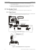
5.1 ACC-25/50 & ACC-25/50DA Step-by-Step Install/Setup
1. Connect the output of the ACC-AAM25 located in the ACC-25/50 to the Audio Riser Input of
each ACC-25/50DA to feed the audio to each distributed panel.
2. Connect the Master Command Output of the ACC-25/50 to the Master Command Inputs of
each ACC-25/50DA for All-Call paging control.
3. Connect the CMD Inputs 1-5 of the ACC-25/50 and the CMD Inputs 1-5 of each ACC-
25/50DA to the FACP as required for automatic control.
4. Set S2 DIP switches on the ACC-25/50DA motherboard as required for AC Loss Reporting,
Background music, CMD input trigger type, and Local Evacuation Backup.
5. Set S1 DIP switches on the ACC-25/50DA motherboard as required for Tone/Message
Control. If the FC-MGM is installed, configure SW1 DIP switches for Leading/Trailing Tone
and Message repeat cycle.
6. Set DIP switches 1, 2 and 3 on S3 of the ACC-25/50 motherboard for Single Zone with
activation of 2-5 messages.
7. Record any new messages into the ACC-25/50ZS and the FC-MGM on the ACC-25/50DA if
required.
8. Faults are monitored by the FACP via the CMD1 Relay, Trouble Relay, and AC Loss Relay.
5.2 ACC-25/50ZS/T & ACC-25/50DAZS Step-by-Step
Install/Setup
1. Connect the output of the ACC-AAM25 located in the ACC-25/50ZS/T to the Audio Riser
Input of each ACC-25/50DAZS to feed the audio to each distributed panel.
2. Connect the EIA-485 serial communications link wiring from the ACC-25/50ZS/T to the
ACC-25/50DAZS for manual and automatic control.
3. Set the address wheels on the ACC-ZPM in the ACC-25/50DAZS for address 01-05, where
ACC-25/50DAZS #1=01, ACC-25/50DAZS #2=02 and so on.
4. Set DIP switches 6, 7, & 8 on S1 of the ACC-ZPMK (in the ACC-25/50ZS/T) for operation
with the number of ACC-25/50DAZS panels (1-5) installed.
5. Set SW1 on the ACC-ZSM of each ACC-25/50DAZS for one or two Audio Amplifier (ACC-
AAM25) configuration.
6. Set SW2 on the ACC-ZSM on each ACC-25/50DAZS for Style Y (Class B) or Style Z (Class
A) speaker circuit wiring.
7. Set S2 DIP switches on the ACC-25/50DAZS motherboard as required for AC Loss Reporting
and Local Evacuation Backup.
8. Set S1 DIP switches on the ACC-25/50DAZS motherboard as required for Tone/Message
Control if Local Evacuation Backup is configured. If the FC-MGM is installed, configure
SW1 DIP switch for Leading/Trailing Tone and Message repeat cycle.
9. Set DIP switches 1, 2, & 3 on S3 of the ACC-25/50ZS/T motherboard for Single Zone with
activation of 2-5 messages.