PN 51480:A0 ECN 01-082 Annunciator Control Modules ACM-16ATF ACM-32AF Instruction Manual Document 51480 02/02/2001 Rev: A
Fire Alarm System Limitations An automatic fire alarm system–typically made up of smoke detectors, heat detectors, manual pull stations, audible warning devices, and a fire alarm control with remote notification capability–can provide early warning of a developing fire. Such a system, however, does not assure protection against property damage or loss of life resulting from a fire.
Installation Precautions WARNING - Several different sources of power can be connected to the fire alarm control panel. Disconnect all sources of power before servicing. Control unit and associated equipment may be damaged by removing and/or inserting cards, modules, or interconnecting cables while the unit is energized. Do not attempt to install, service, or operate this unit until this manual is read and understood. CAUTION - System Reacceptance Test after Software Changes.
This page intentionally left blank 4 ACM-16ATF/ACM-32AF Manual PN 51480:A0 02/02/01
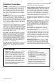
Table of Contents Table of Contents 1. Product Overview General................................................................................................... 9 Canadian Information........................................................................ 10 Related Documentation ...................................................................... 10 2. Inventory ACM-16ATF Series ............................................................................ 11 Control Modules............................
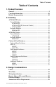
Table of Contents 4. Installation Mounting the Backbox or Cabinet ................................................... 23 Wiring and Connecting...................................................................... 23 Connect Wiring to Backbox or Cabinet........................................... 24 When the EIA-485 shield is not in conduit: ................................ 24 When the EIA-485 shield is in conduit: ...................................... 24 EIA-485 Circuit ....................................
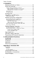
Table of Contents Appendix B: Sensiscan 2000 Capabilities.......................................................................................... 47 Circuits: ............................................................................................ 47 System Controls: .............................................................................. 47 Configuring for the Sensiscan 2000................................................... 47 Connecting the EIA-485 Circuit....................................
This Page Intentionally Left Blank 8 ACM-16ATF/ACM-32AF Manual PN 51480:A0 02/02/01
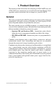
1. Product Overview This manual provides instructions for connecting an ACM-16ATF series and ACM-32AF series annunciators to various Fire Alarm Control Panels. Each appendix contains instructions that are unique to a particular FACP. General This series provides Fire•Lite FACPs with up to 32 remote serially connected annunciators, each with a capacity of 64 points, for a total capacity of 2048 points. Expander modules are provided for each series.
1. Product Overview Canadian Information Canadian Information The National Standard of Canada (CAN/ULC-S527) requires that a dedicated display employ yellow visual indicators to indicate the status of supervisory inputs. The Fire•Lite annunciators listed in this manual are intended to be used for Canadian Supervisory Service in conjunction with Fire•Lite Sensiscan 200, Sensicsan 2000, MS-9200 and MS-9600 control units.
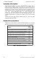
2. Inventory ACM-16ATF Series Control Modules ACM-16ATF Height = 8-3/8" (21.27 cm) Width = 4-3/8" (11.11 cm). Note: In Canada this module must be used to annunciate the fire alarm input points/zones only. ACM-16AT.
2. Inventory ACM-16ATF Series Expander Modules AEM-16ATF Expands the ACM-16ATF Series by 16 system points. The unit is identical in size and in frontal appearance to the control module. One to three of these expander modules can be supported by a control module to a maximum of 64 system points. Note: The AEM-16ATF Series cannot be used to expand the ACM-32AF. Expander LED colors need not match the control module LED colors for the expander to operate.
ACM-32AF Series 2. Inventory ACM-32AF Series Control Modules ACM-32AF This control module contains 32 red “point active” LEDs, a system “trouble” LED, an On-line/Power LED, and a local piezo sounder with a silence/acknowledge switch for audible indication of alarm and trouble conditions at each annunciator. Note: In Canada this module must be used to annunciate the fire alarm input points/zones only. ACM-32A.cdr Height = 8-3/8" (21.27 cm) Width = 4-3/8" (11.11 cm).
2. Inventory Cabinet & Panel Hardware Cabinet & Panel Hardware Surface-Mount Backboxes ABS-1F This surface mounted backbox provides for the remote mounting of a single ACM-16ATF Series or ACM32AF Series annunciator in a surface-mount enclosure. Knockouts are provided for use with 1/2" conduit. The annunciator mounts directly to the box without a dress plate. 50439d2.tif Height = 8-1/2" (21.59 cm) Width = 4-1/2" (11.43 cm) Depth = 1-3/8" (3.49 cm).
2. Inventory Cabinet & Panel Hardware Flush-mount Backboxes ABF-1F Height = 9-15/16" (25.24 cm) Width = 4-5/8" (11.75 cm) Depth = 2-1/2" (6.35 cm). Trim Plate dimensions 11" (27.94 cm) x 6-1/4" (15.875 cm) 50439d3.tif This flush mounted backbox provides for the remote mounting of a single annunciator module in a flush-mount enclosure. Knockouts are provided for use with 1/2" conduit. Includes a trim plate, mounting hardware, and an adhesive-backed annunciator label for the dress plate (15824).
2. Inventory Cabinet & Panel Hardware Semi Flush-mount Backboxes ABF-1DF This backbox mounts one Annunciator module and includes an attractive smoked glass door with keylock. Box dimensions Height = 9-15/16" (25.24 cm) Width = 4-5/8" (11.75 cm) depth = 2-1/2" (6.35 cm). ABF-1DF.cdr Door dimensions Height = 10.713" (27.21 cm) Width = 6" (15.24 cm) Depth = 0.75" (1.9 cm). ABF-2DF Same as ABF-1DF except that two modules can be mounted. Box dimensions Height = 9-15/16" (25.24 cm) Width = 9-3/16" (23.
Cabinet & Panel Hardware 2. Inventory Additional Hardware ABM-1 The Annunciator Blank Module is a two-sided dress plate identical in appearance to the front panel of the ACM-16ATF module on one side, and the front panel of the ACM-32AF module on the other side. The blank module covers unused module positions in the annunciator backbox or dress panel. Height = 8-3/8" (21.27 cm), Width = 4-3/8" (11.11 cm).
2.
3. Design Considerations Limits The standard Fire•Lite EIA-485 circuit can drive up to 32 annunciators or expanders. The number of annunciators that can engage in two-way communication is dependent on the number of addresses available with a given fire alarm control panel. The actual number of annunciator/expander modules that can be powered in a particular system depends on the current available from the control panel’s power supply.
3. Design Considerations Receive Only and Transmit/Receive Receive Only and Transmit/Receive For redundant annunciation of system points, annunciators can be configured as “Receive Only” annunciators. Receive Only annunciators must be set to the same address as the annunciators they duplicate. Receive Only annunciators intercept information being transmitted to a “Receive/Transmit” annunciator for duplication at an intermediate display location.
3. Design Considerations Electrical Ratings Electrical Ratings Input Voltage: 24 VDC (must be filtered and power-limited). Current Draw from 24 VDC Input: Standby Alarm ACM-16ATF & ACM-32AF Series 0.040 amps 0.056 amps AEM-16ATF & AEM-32AF Series 0.002 amps 0.018 amps Data Communications Port: EIA-485 operating at 20 Kbps (must be powerlimited).
3.
4. Installation This section provides detailed instructions for installing and wiring annunciator modules and expander modules. Note: For wiring & programming details that are unique to a specific fire alarm control panel, refer to that panel's appendix in this manual, and to the panel's Instruction Manual. Mounting the Backbox or Cabinet Select appropriate knockout(s) on the enclosure for your wiring to run through and snap it out. Fasten the cabinet or backbox to the wall.
4. Installation Wiring and Connecting Connect Wiring to Backbox or Cabinet Pull all annunciator wiring into the enclosure and terminate as stated and illustrated below: When the EIA-485 shield is not in conduit: • Terminate the shield at the outside of the FACP backbox (ground). • Do not allow the shield to enter or even touch the cabinet. • Between annunciators, wire-nut multiple shields together outside of the respective enclosures. ACSf-term1.
4. Installation Wiring and Connecting EIA-485 Circuit Connect the EIA-485 annunciator circuit wiring to the removable terminal blocks as illustrated below. • Do not “T-Tap” the power-limited EIA-485 circuit. It will not function properly. • Leave the 120-ohm ELR (PN 71244) installed across the EIA-485 ‘Out’ terminals at the last annunciator on the circuit. Remove this resistor from all other annunciators.
4. Installation Wiring and Connecting 24 VDC Circuit ! CAUTION: Power must be turned off when connecting the 24 VDC power to the annunciator to avoid damaging the equipment. Connect the 24 VDC annunciator wiring to the removable terminal blocks as illustrated below: • Power must be filtered, non-resettable, and power-limited.
4. Installation Installing Labels Installing Labels ACSf-labels.cdr Remove the center pages of this manual. If using the custom user display labels, type the appropriate information on the labels. Carefully cut out the labels and insert them into the annunciator or expander by slipping them into the label slots on the back side of the annunciator face plate. To ensure the best fit, cut directly along the dotted line surrounding each label.
4. Installation Setting Rotary and DIP Switches Setting Rotary and DIP Switches The Annunciator Address Rotory Switches and the DIP Switches must be set before the annunciator will operate properly. The rotory switches are set to the addresss of the annunciator. The DIP switches are set to determine how the annunciator operates. For further information see the appendix for the specific FACP.
4. Installation Mounting Annunciators and Expanders Mounting Annunciators and Expanders Set the address Rotory Switches and DIP Switches as outlined in "Setting Rotary and DIP Switches" on page 28 and the Appendix for specific fire alarm control panels. Install labels in annunciator module and expander module(s) as detailed in "Installing Labels" on page 27. Surface Mount Backbox (ABS Series) 1. Connect terminal blocks on circuit wiring in backbox to connectors on annunciator. 2.
4. Installation Mounting Annunciators and Expanders 3. If employing an AKS-1F Key Switch, mount it to the trim plate. Plug the switch leads to connector J4 on the annunciator. J4 Connector ACSf-akswire.cdr AKS-1F Key Switch Figure 11 Annunciator Key Switch 4. Plug terminal blocks on circuit wiring in backbox to connectors on annunciator. 5. Align the mounting holes on the trim plate with the threaded tabs on the backbox and secure with the two screws provided. Tighten securely.
4. Installation Wiring the Expander Connections Semi-Flush Mount Backbox (ABF-1DF/-2DF) Annunciators and expanders are mounted in these backboxes the same way as they are mounted in the flush mounted type, except for the addition of the following: Aligning the door with the trim plate, slide it down onto the pins of the trim plate. When positioned correctly, the door will open and close freely. Close and lock door. Dress Panel (ADP-4F) 1.
4. Installation Wiring the Expander Connections Four Position Backbox (-4 Series) or Cabinet ACM-16 Series/AEM-16ATF If installing one ACM-16 Series annunciator with three AEM-16ATF expanders on the same trim plate or dress panel, perform the following steps: • Plug one end of an Expander Ribbon Cable into connector J2 on the annunciator module. Place the expander module in the second position. Connect the ribbon cable from the annunciator module to connector J3 on the expander module.
4. Installation Supervising Devices Supervising Devices The normally closed Trouble Input can be used for supervising local power sources or other devices. If employed, all changes in status (to and from the trouble state) will be sent to the control panel in the event of device failure or restoral. If not used, a jumper must be installed across the terminals. Without this jumper, the control panel will register a trouble condition. TB1 on Annunciator Device to be supervised 5 VDC @ 0.
Remove Center Pages for Slide-In Labels ACM-16ATF & AEM-16ATF Labels Two labels are required for the ACM-16ATF or the AEM-16ATF, one for the left side and one for the right side of each module. Each label has a distinctive format. See "Installing Labels" on page 27 for more information on these labels. Set A: Sensiscan 200 & Sensiscan 2000 - A label set that provides a label (#1) for system control functions & system status, and blank labels (#2 - #7) for one control module and three expander modules.
Remove Center Pages for Slide-In Labels ACM-32AF & AEM-32AF Labels Two labels are required for the ACM-32AF or the AEM-32AF, one for the left side and one for the right side of each module. Each label has a distinctive format. See "Installing Labels" on page 27 for more information on these labels. Set E: Sensiscan 200 & Sensiscan 2000 - A label set that provides a label (#1) for system status, and blank labels (#2 - #4) for one control module and one expander modules.
NOTES 36 ACM-16ATF/ACM-32AF Manual PN 51480:A0 02/02/01
5. LED and Switch Functions ACM-16ATF The following is a description of the various LEDs and switches located on the ACM-16ATF. Local Silence/Acknowledge Switch On-Line LED System Trouble LED Point-Active LED Trouble LED ACM-16AT.cdr Control Switch Figure 14 ACM Series LED & Switch Locations Local Silence/Acknowledge Switch - This switch performs multiple functions: • When pressed, it first lights all the LEDs (except the On-line LED) on the module and then each expander.
5. LED and Switch Functions ACM-16ATF System Trouble LED - Glows yellow for all trouble conditions in the system, including points or zones not mapped to the annunciator/expanders. Point-Active LED - Flashes to indicate an active point; after being acknowledged it glows until reset. Note: LED color varies by model number; see chart below. Trouble LED - Flashes to indicate a trouble situation. After being acknowledged it glows until reset.
AEM-16ATF 5. LED and Switch Functions AEM-16ATF The following is a description of the various LEDs and switches located on the AEM-16ATF. Lamp Test Switch Inactive LEDs Point-Active LED Trouble LED AEM-16AT.cdr Control Switch Figure 15 AEM-16ATF Series LED & Switch Locations Lamp Test Switch - When pressed, it lights all the LEDs (except the Online LED) on the expander and sounds the piezo for as long as the switch is held down. Inactive LEDs - These two LEDs are not functional on expander modules.
5. LED and Switch Functions ACM-32AF ACM-32AF The following is a description of the LEDs and the switch located on the ACM-32AF. Local Silence/Acknowledge Switch On-Line LED System Trouble LED ACM-32A.cdr Point-Active LED Figure 16 ACM-32AF LED & Switch Locations Local Silence/Acknowledge Switch - This switch performs multiple functions: • When pressed, it first lights all the LEDs (except the On-line LED) on the annunciator and then each expander. Piezo sounds for as long as the switch is held down.
5. LED and Switch Functions AEM-32AF AEM-32AF The following is a description of the LEDs and the switch located on the AEM-32AF. Lamp Test Switch Inactive LED AEM-32A.cdr Point-Active LED Figure 17 AEM-32AF LED & Switch Locations Lamp Test Switch - When pressed, it lights all the LEDs (except the Online LED) on the expander module and sounds the piezo for as long as the switch is held down. Inactive LEDs - These two LEDs are not functional on expander modules.
5.
Appendix A: Sensiscan 200 Capabilities When installed with a Sensiscan 200, the modules can annunciate the status of initiating and notification circuits, relays, and several system control functions. Up to 32 devices can be connected to the EIA-485 communications output, all addresses combined. Two way communications can occur with only one annunciator set to address “1”; other devices must be configured as “Receive Only”. Check battery calculation tables for power limitations.
Appendix A: Sensiscan 200 Providing Power to Annunciators This communication circuit is supervised by the Sensiscan 200. Loss of communication results in “System Trouble” and “Module Failure” indications at the CPU. Note: “System Trouble” and “Module Failure” will occur if the normally closed supervisory path between Trouble Input Terminals of TB1 on the annunciator is opened (or the jumper has not been installed).
Appendix A: Sensiscan 200 Program Mapping Program Mapping Annunciator points “track” or follow those system points they are programmed to annunciate; they do not latch. The table outlines the annunciation of various system circuits and functions. Note: Control Switches marked “not used” will still function as local LAMP TEST or local ACKNOWLEDGE switches for their respective points.
Appendix A: Sensiscan 200 Program Mapping NOTES 46 ACM-16ATF/ACM-32AF Manual PN 51480:A0 02/02/01
Appendix B: Sensiscan 2000 Capabilities When installed with a Sensiscan 2000, the modules can annunciate the status of initiating and notification circuits, relays, and several system control functions. Each annunciator LED is automatically assigned to one and only one system point. Note: To operate the annunciator module, the CPU must be Revision D or greater. The revision level of the CPU is marked on a label affixed to the upper board.
Appendix B: Sensiscan 2000 Connecting the EIA-485 Circuit Connecting the EIA-485 Circuit Communication between the control panel and the annunciator module is accomplished over a two-wire EIA-485 serial interface. • Power-limited and supervised. • 6000 feet maximum distance (with 16 AWG wire) between the control panel and the furthest annunciator. • Use twisted pair cable with a characteristic impedance of approximately 120 ohms. • EIA-485 circuit rated 5.5 VDC max., 60 mA max.
Appendix B: Sensiscan 2000 Providing Power to Annunciators Providing Power to Annunciators Sensiscan 2000 panels use the MPS-24AF or the MPS-24BF Main Power Supply. This 24 VDC output is filtered, regulated, power-limited, and nonresettable. MPS-24AF - 3 A maximum current draw MPS-24BF - 200 mA maximum current draw The power run to the annunciator does not require a Power Supervision Relay because loss of power is inherently supervised through a communications loss.
Appendix B: Sensiscan 2000 Installing Modules in the System Installing Modules in the System The annunciator modules begin annunciation with the CPU and continue with the annunciation of circuits on the module installed directly after the CPU. To ensure full employment of annunciator points, mount system modules that require annunciation in the CPU row first, then in the second row, etc. Modules with circuits that need not be annunciated by the system should be installed further down in the cabinet.
Appendix B: Sensiscan 2000 Program Mapping Program Mapping Annunciator points “track” or follow those system points they are programmed to annunciate; they do not latch. The table outlines the annunciation of various system circuits and functions. Note: Control Switches marked “not used” will still function as local LAMP TEST or local ACKNOWLEDGE switches for their respective points.
Appendix B: Sensiscan 2000 Program Mapping NOTES 52 ACM-16ATF/ACM-32AF Manual PN 51480:A0 02/02/01
Appendix C: MS-9200 Capabilities The MS-9200 allows annunciators to be programmed by zone or by point. The EIA-485 serial interface will allow up to 32 annunciators, but two-way communications can occur with only one annunciator per address. The other devices must be configured as “Receive Only”. When the panel is programmed by zone, annunciator address 1 is available, and the annunciator modules display the 56 software zones of the MS-9200. When the panel is programmed by point, 198 points are available.
Appendix C: MS-9200 Providing Power to Annunciators The EIA-485 circuit is connected between the ACS Mode connector (TB5) on the main circuit board to terminal TB2 on the annunciator (see Figure 5 on page 25). – A CS 1 C OMM 2 S HIE L D A B S LC B+ S LC A+ B- AT B 6 TB5 - ACS Mode connector TB2 ACSf-9200.cdr + T B 5 Figure 24 EIA-485 Circuit Connections - MS-9200 Providing Power to Annunciators The MS-9200’s 24 VDC main power supply is contained on its main circuit board.
Appendix C: MS-9200 Program Mapping Program Mapping Annunciator points “track” or follow those system points they are programmed to annunciate; they do not latch. The table outlines the annunciation of system functions. Note: Control Switches marked “No Function” will still function as local LAMP TEST or local ACKNOWLEDGE switches for their respective points.
Appendix C: MS-9200 Program Mapping NOTES 56 ACM-16ATF/ACM-32AF Manual PN 51480:A0 02/02/01
Appendix D: MS-9600 Capabilities The MS-9600 allows annunciators to be programmed by zone or by point. The EIA-485 serial interface will allow up to 32 annunciators, but two-way communications can occur with only one annunciator per address. The other devices must be configured as “Receive Only”. When the panel is programmed by zone, annunciator address 1 is available, and the annunciator modules displays the 99 software zones of the MS-9600.
Appendix D: MS-9600 Providing Power to Annunciators + – TB2 TB6 TB6 - ACS EIA-485 connector ACSf-9600.cdr The EIA-485 circuit is connected between the ACS EIA-485 connector (TB6) on the main circuit board to terminal TB2 on the annunciator (see Figure 5 on page 25). Figure 26 EIA-485 Circuit Connections - MS-9600 Providing Power to Annunciators The MS-9600’s 24 VDC main power supply is contained on its main circuit board.
Appendix D: MS-9600 Program Mapping Program Mapping Annunciator points “track” or follow those system points they are programmed to annunciate; they do not latch. The table outlines the annunciation of system functions. Note: Control Switches marked “No Function” will still function as local LAMP TEST or local ACKNOWLEDGE switches for their respective points.
Appendix D: MS-9600 Program Mapping NOTES 60 ACM-16ATF/ACM-32AF Manual PN 51480:A0 02/02/01
Index Index Numerics 120 volts AC 19 120-ohm ELR 25, 32 120-volt AC 23 24 VDC 19, 21, 26, 44, 49 24 VDC main power supply 54, 58 A D ACKNOWLEDGE 38, 39, 45, 51, 55, 59 Acknowledge 20 Acknowledge switch 28 ACS EIA-485 connector 58 ACS Mode connector 54 active point 39, 40, 41 Address Rotory Switches 28 addresses available 19 AKS-1F 29, 30 Alarm Current 21 annunciator address 50, 53, 57 annunciator points 41, 45, 51, 55, 59 APS-6RF dedicated display 10 device failure or restoral 33 DIP Switches 28, 29
Index I impedance 19, 23, 43, 48, 53, 57 Inactive LEDs 39, 41 Initiating Device Circuits 43, 47 Input Voltage 21 intermediate display 20 N J J2 31, 32 J3 31, 32 J4 28, 30 jumper 33, NACs 53, 57 National Standard of Canada 10 non-resettable 26, 44, 49, 54, 58 Notification Appliance Circuits 43, 44, 48, 53, 57 47 K O Key Switch 17, 29, 30 Key Switch Connector 28 keylock 16 knockout 23 On-line LED label 15, 17, 30 label slots 27 labels 27, 29 LAMP TEST 45, 51, 55, 59 Lamp Test 20, 38, 39 Lamp Test S
Index remote power supply Reset 20 resistance 19 ribbon cable 31, 32 Rotory Switches 28, 26 terminal blocks 25, 26, 29, 30, 31, 32 test the system 33 threaded tabs 29, 30 touch-pad switches 11 transmit commands 20 Transmit/Receive 20 trim plate 15, 29, 30 trouble condition 33, 38, Trouble Input 33 Trouble LED 38, 39 trouble LEDs 41 trouble situation 39 T-Tap 25 T-Tapped 19 29 S second set 32 secondary power supply 21 serial interface 9 shield 23, 24 SIGNAL SILENCE 38, 39 signal silence 9 Silence 20 Sil
ACM-16ATF/ACM-32AF Manual PN 51480:A0 02/02/01
ACM-16ATF/ACM-32AF Manual PN 51480:A0 02/02/01 65
ACM-16ATF/ACM-32AF Manual PN 51480:A0 02/02/01
Limited Warranty The manufacturer warrants its products to be free from defects in materials and workmanship for eighteen (18) months from the date of manufacture, under normal use and service. Products are date-stamped at time of manufacture. The sole and exclusive obligation of the manufacturer is to repair or replace, at its option, free of charge for parts and labor, any part which is defective in materials or workmanship under normal use and service.
World Headquarters One Fire-Lite Place, Northford, CT 06472-1653 USA 203-484-7161 • Fax 203-484-7118 www.firelite.