
Instruction Manual
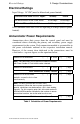


Electrical Ratings 3. Design Considerations
ACM-16ATF/ACM-32AF Manual PN 51480:A0 02/02/01
21
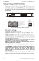
Electrical Ratings
Input Voltage: 24 VDC (must be filtered and power-limited).
Data Communications Port: EIA-485 operating at 20 Kbps (must be power-
limited).
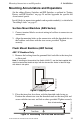
Annunciator Power Requirements
Annunciators draw their power from the control panel and must be
considered when calculating the primary and secondary power supply
requirements for the system. Each annunciator module is accounted for in
the power calculations outlined in the respective installation manual.
However, if the current draw dedicated to the annunciators must be
calculated as a separate figure, use the equations below:
Table 2 Calculation of Power Requirements
Current Draw from 24 VDC Input: Standby Alarm
ACM-16ATF & ACM-32AF Series 0.040 amps 0.056 amps
AEM-16ATF & AEM-32AF Series 0.002 amps 0.018 amps
Number of ACM modules [ ] X 0.040 = [ ] amps
Note: The 0.040 amps can be reduced to 0.030 for modules
with Piezo Disable or Flash Inhibit modes selected.
Number of AEM modules [ ] X 0.002 = [ ] amps
Total Annunciator Standby Current = [ ] amps
Number of ACM and AEM
modules assumed to be in alarm
simultaneously
[ ] X 0.016 = [ ] amps
Note: This entry assumes that all LEDs are lit
simultaneously. When the alarm system specification
permits, calculations can be based on a 10% alarm loading
capacity. For 10% capacity, enter 10% of the total number of
ACM and AEM modules multiplied by the number of remote
annunciator locations, but do not enter less than one.
Total Annunciator Alarm Current = [ ] amps