
Instruction Manual


Appendix A: Sensiscan 200 Providing Power to Annunciators
44
ACM-16ATF/ACM-32AF Manual PN 51480:A0 02/02/01
This communication circuit is supervised by the Sensiscan 200. Loss of
communication results in “System Trouble” and “Module Failure”
indications at the CPU.
Note: “System Trouble” and “Module Failure” will occur if the normally closed
supervisory path between Trouble Input Terminals of TB1 on the annunciator is
opened (or the jumper has not been installed).
The EIA-485 circuit is connected between the EIA-485 Interface on the CPU
and terminal TB2 on the annunciator.
Figure 18 EIA-484 Circuit Connections - Sensiscan 200
Providing Power to Annunciators
Sensiscan 200 panels use the MPS-24BF Main Power Supply. No more than
200mA current can be drawn from these terminals in standby or alarm. This
24 VDC output is filtered, regulated, power-limited, and non-resettable.
The power run to the annunciator does not require a Power Supervision Relay
because loss of power is inherently supervised through a communications
loss.
Note: When not using the trouble input on annunciator or expander, jumper Trouble
Input terminals of TB1 on annunciator together.
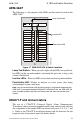
Connect the power run for the annunciator module to TB2 Terminals 3(+)
and 4(–) as shown below.
Figure 19 Power Connections - Sensiscan 200
– +
ACSf-s200.cdr
EIA-485 Interface
on CPU of the
Sensiscan 200
TB2
TB3
TB2
BATT –BATT +
COMMON COMMON
1 2 3 4
1 2
ACSf-mps24b.cdr
(–) Common
(+) 24 VDC Non-Resettable Power
TB1
MPS-24BF Terminal Blocks