
Instruction Manual


Program Mapping Appendix B: Sensiscan 2000
ACM-16ATF/ACM-32AF Manual PN 51480:A0 02/02/01
51
Program Mapping
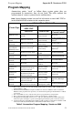
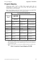
Annunciator points “track” or follow those system points they are
programmed to annunciate; they do not latch. The table outlines the
annunciation of various system circuits and functions.
Note: Control Switches marked “not used” will still function as local LAMP TEST or
local ACKNOWLEDGE switches for their respective points.
Table 5 Annunciator Program Mapping - Sensiscan 2000
Circuit Type
ACM-16ATF & AEM-16ATF
ACM-32AF
AEM-32AF
Red LED Yellow LED
Control Switch
1
IZM-8F circuit
Indicates alarm status of
circuit
2
Indicates trouble
status of circuit
Not used
ICM-4F, ICE-4F
circuit
Indicates Activation
3
Indicates trouble
status of circuit
Controls Notification
Circuit
4
CRM-4F, CRE-
4F circuit
Indicates Activation
3
Indicates trouble
status of relay
Controls Relays
4
TCM-2F, TCM-
4F, VCM-4F,
DCM-4F circuit
Indicates Activation
3
Indicates trouble
status of relay
Remote Switch
Functions
4
Annunciator
Point #1
5
Indicates System Alarm
Indicates System
Trouble
ACKNOWLEDGE
Annunciator
Point #2
Not used
Indicates that signals
have been silenced
SIGNAL SILENCE
Annunciator
Point #3
Not used Not used SYSTEM RESET
Annunciator
Point #4
Not used
Indicates Supervisory
condition
Not used
Annunciator
Point #5
Indicates that
Notification Circuit #1
has been activated
Indicates trouble
status of circuit
Controls Notification
Circuit #1
Annunciator
Point #6
Indicates that
Notification Circuit #2
has been activated
Indicates trouble
status of circuit
Controls Notification
Circuit #2
Annunciator
Point #7
Indicates that Remote
Signaling Municipal Tie
has been activated
Indicates trouble
status of circuit
6
Controls Remote
Signaling Municipal
Tie
Annunciator
Point #8
Indicates that Alarm
Relay has been activated
Indicates AC fail
module/panel trouble
Controls Alarm Relay
1. These control switches are active only if: DIP Switch #5 (Receive Only) is ‘OFF’ and DIP Switch #7
(Switch Inhibit) is ‘OFF’.
2. With Software P/N #S500R4.0 or higher installed in the Sensiscan 2000, the manner in which the
IZM-8F circuits programmed as supervisory are annunciated depends upon whether Mode 1 or Mode
2 is selected.
3. These status LEDs are active only when the system is programmed for “Output Status”.
4. These control switches require that the system be programmed for “Output Control”.
5. If the Eight-Point Shift (DIP switch # 4) is set “ON,” the eight CPU functions will be shifted from
annunciator points 1 through 8 to points 57 through 64 (provided those points exist in the system).
6. Annunciator Point #7 yellow LED indicates Municipal Tie trouble if no UDACT-F is installed. It will
annunciate Low Battery/Ground Fault if a UDACT-F is installed in the system.