
Instruction Manual
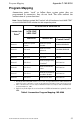


Appendix C: MS-9200 Providing Power to Annunciators
54
ACM-16ATF/ACM-32AF Manual PN 51480:A0 02/02/01
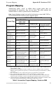
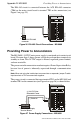
The EIA-485 circuit is connected between the ACS Mode connector (TB5)
on the main circuit board to terminal TB2 on the annunciator (see Figure 5
on page 25).
Figure 24 EIA-485 Circuit Connections - MS-9200
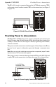
Providing Power to Annunciators
The MS-9200’s 24 VDC main power supply is contained on its main circuit
board. No more than 300 mA current can be drawn from these terminals in
standby or alarm. This 24 VDC output is filtered, regulated, power-limited,
and non-resettable.
The power run to the annunciator need not require a Power Supervision Relay
because loss of power is inherently supervised through a communication
loss.
Note: When not using the trouble input on annunciator or expander, jumper Trouble
Input terminals of TB1 on annunciator together.
The power circuit is connected between terminal TB4 on the MS-9200 and
terminal TB1 on the annunciator (see Figure 6 on page 26) as shown below.
Figure 25 Power Supply Connections - MS-9200
+ –
A B B+ A+ B- A-
1 COMM 2
ACS SHIELD SLC SLC
T
B
5
T
B
6
ACSf-9200.cdr
TB2
TB5 - ACS Mode
connector
+ –
24V UNREG 24V NONRS 24V RST
T
B
4
ACSf-9200pwr.cdr
TB1
TB4 - Power Supply
Terminal Blocks
(+) 24 VDC Non-
Resettable Power
(–) Common