
Instruction Manual


Program Mapping Appendix D: MS-9600
ACM-16ATF/ACM-32AF Manual PN 51480:A0 02/02/01
59
Program Mapping
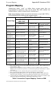
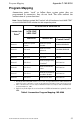
Annunciator points “track” or follow those system points they are
programmed to annunciate; they do not latch. The table outlines the
annunciation of system functions.
Note: Control Switches marked “No Function” will still function as local LAMP TEST
or local ACKNOWLEDGE switches for their respective points.
Table 7 Annunciator Program Mapping - MS-9600
Annunciator
Point
1
ACM-16ATF & AEM-16ATF
ACM-32AF
AEM-32AF
Red LED Yellow LED
Control Switch
2
Point #1
Indicates System
Alarm
Indicates System
Trouble
ACKNOWLEDGE
Point #2 Not used
Indicates Alarm
Silenced
ALARM SILENCE
Point #3 Not used
Indicates Program
Mode
SYSTEM RESET
Point #4 Not used
Indicates Supervisory
Condition
3
DRILL
Point #5 Not Used
Indicates NAC
Trouble
No Function
Point #6 Not Used Indicates Walktest No Function
Point #7 Not Used Indicates Low Battery No Function
Point #8 Not Used Indicates AC Fail No Function
1. If the Eight-Point Shift (DIP switch # 4) is set “ON,” the eight CPU functions will be shifted from
annunciator points 1 through 8 to points 57 through 64 (provided those points exist in the system).
2. These control switches are active only if: DIP Switch #5 (Receive Only) is ‘OFF’ and DIP Switch
#7 (Switch Inhibit) is ‘OFF’.
3. Supervisory Point lights its associated zone red LED and annunciator point #5 yellow
LED.