G PN 50362:C0 ECN 01-155 Control Relay Module ACM-8RF Instruction Manual Document 50362 03/21/2001 Rev: C
Fire Alarm System Limitations An automatic fire alarm system–typically made up of smoke detectors, heat detectors, manual pull stations, audible warning devices, and a fire alarm control with remote notification capability–can provide early warning of a developing fire. Such a system, however, does not assure protection against property damage or loss of life resulting from a fire.
Installation Precautions WARNING - Several different sources of power can be connected to the fire alarm control panel. Disconnect all sources of power before servicing. Control unit and associated equipment may be damaged by removing and/or inserting cards, modules, or interconnecting cables while the unit is energized. Do not attempt to install, service, or operate this unit until this manual is read and understood. CAUTION - System Reacceptance Test after Software Changes.
This page intentionally left blank 4 ACM-8RF PN 50362:C 03/21/01
Table of Contents Table of Contents 1. Introduction General................................................................................................... 7 Mounting ............................................................................................... 7 Features ................................................................................................. 8 Relays .................................................................................................
Table of Contents Appendix B: MS-9200 Capabilities ..........................................................................................31 Testing..................................................................................................31 Wiring ..................................................................................................31 FACP Activations ...............................................................................32 Alarm Only Activation ..............................
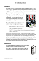
1. Introduction General The ACM-8RF Relay Control Module contains eight high current (5 amps) Form-C relays. The module interfaces to host Fire•Lite control panels which employ an EIA-485 communications bus and may be connected to the bus up to 6,000 feet away from the host control panel. 1 2 FF O Typically, each relay is assigned to a zone on the host fire alarm control panel. The relays may be triggered by either a zone alarm (activation) or zone trouble.
1. Introduction Features Features SW3 - Relay Assignment DIP Switches K4 K5 Relays K3 K6 K2 K7 K1 K8 FF O 1 2 O 1 F F 2 3 4 5 6 7 ACM-8RF.cdr Relays 8 SW4 - Mode Select Switch TB2 - EIA-485 Terminal Block SW1-SW2 Address Select Rotary Switches TB1 - 24 VDC Terminal Block Figure 1 ACM-8RF Features Relays The Relay Control Module provides eight Form-C relays with 5 amp contacts @ 125 VAC (resistive) or 30 VDC (resistive) and 2 amps at 125 VAC inductive).
1. Introduction Related Documentation EIA-485 Communications Wiring to removable terminal block TB2 is for communications over the EIA485 bus. The bus carries commands and data sent between the host FACP and ACM-8RFs. The EIA-485 circuit is power-limited. The host FACP supervises devices wired to the EIA-485 bus.
1.
2. Installation Mounting the Enclosure. Select and remove the appropriate knockout(s) on the ABS-8RF enclosure. Securely mount the enclosure. Ground the enclosure to a solid electrical ground per NEC Article 250. Pull all wiring into the enclosure (refer to "UL Power-limited Wiring Requirements" on page 17). Wiring the Power Terminal Blocks 24 VDC power supplied by the host control panel or external power supply must be regulated and power-limited.
2. Installation Wiring the Relay Terminal Blocks Wiring the Relay Terminal Blocks The ACM-8RF provides eight relays with Form-C contacts rated for 5 amps. Note: Wiring from these relays is not supervised. The terminal assignments are illustrated below. For information on wiring limitations, refer to "UL Power-limited Wiring Requirements" on page 17.
2. Installation Wiring the EIA-485 Terminal Blocks Wiring the EIA-485 Terminal Blocks Communications between the Fire Alarm Control Panel and the ACM-8RF is accomplished over a two-wire EIA-485 serial communications bus which must be power-limited. Communications between the host FACP and ACM-8RFs is supervised by the fire alarm control panel. Wiring Specifications • The EIA-485 circuit cannot be T-tapped; it must be wired in a continuous fashion from the control panel to the ACM-8RFs.
2. Installation Wiring the EIA-485 Terminal Blocks EIA-485 Shield Not in Conduit When the EIA-485 wiring is not in conduit, terminate the shield at the outside of the FACP cabinet. Do not allow the shield to enter or even touch the cabinet housing the ACM-8RFs. Between ACM-8RFs, wire-nut multiple shields together outside of the respective enclosures. Ensure that the shield does not touch earth ground at any junction points. TB 2 ACM8RF-term2.
2. Installation Configuring the ACM-8RF Configuring the ACM-8RF Address Switches - SW1 and SW2 It is critical to the operation of the relays that the address switches be set correctly. TENS ONES SW 2 SW 1 ACM8RF-SW1-2.cdr To set the relay module for address ‘01’, position the arrow on SW1 (tens) so it points to 0 and position the arrow on SW2 (ones) so it points to 1.
2. Installation Mounting in the ABS-8RF Enclosure Mode Select Switch - SW4 Set the mode of operation as follows: ALM O N LY RCV O N LY M O DE SELE CT ACM8RF-SW4.cdr 1 2 Figure 11 Mode Select Switch • Switch #1 set to the ON position will cause the ACM-8RF relays to trigger only for FACP zone alarm activation. • Switch #1 set to the OFF position will cause the ACM-8RF relays to trigger for FACP zone alarm and zone trouble activation.
2. Installation UL Power-limited Wiring Requirements UL Power-limited Wiring Requirements Power-limited and nonpower-limited circuit wiring must remain separated in the cabinet. All power-limited circuit wiring must remain at least 0.25" away from any nonpower-limited circuit wiring. Furthermore, all power-limited circuit wiring and nonpower-limited circuit wiring must enter and exit the cabinet through different knockouts and/or conduits. A typical wiring diagram for the ACM-8RF is shown below.
2.
3. Electrical Ratings 24 VDC Must be power-limited. Current Draw from 24 VDC Input @ Normal Standby: 0.030 amps Maximum current with all output relays activated: 158 mA. Relay Contacts UL contact ratings are 5 amps @ 125 VAC (resistive) or 30 VDC (resistive) and 2 amps @ 125 VAC (inductive). Data Communications Port Must be power-limited.
3.
Appendix A: MS-5210UD Capabilities When installed with an MS-5210UD Fire Alarm Control Panel (FACP), the ACM-8RF Relay Control Modules provide relay activation for each of the ten FACP zones plus special functions. Options exist to allow for alarm only or alarm and trouble activations per zone. Output activation for General Alarm, general trouble, general Supervisory, NAC Fault, AC Fail, System Off Normal, Walktest start and Battery Trouble are also available.
Appendix A: MS-5210UD FACP Activations FACP Activations DIP switch SW3 on the ACM-8RF Relay Control Module is used to determine which FACP activations will trigger relays on the Relay Control Module. When installed with an MS-5210UD Fire Alarm Control Panel, use the following tables to set SW3 switches. Note that two tables are provided; one table for alarm only operation (SW4-1 = ON) and one table for alarm and trouble operation (SW4-1 = OFF).
Appendix A: MS-5210UD FACP Activations Alarm and Trouble Activation Table 5 provides the switch settings for ACM-8RF DIP switch SW3 when configuring the relays to trigger for alarm and trouble activation. Note that a maximum of five ACM-8RFs are required if relays are to be designated to trigger on any FACP status change. If system status relays are not required, three ACM-8RFs may be used to allow individual relay triggering for alarm and trouble activation of FACP zones 1 through 10.
Appendix A: MS-5210UD Application Example #1 Application Example #1 Zone Alarm Only Activation (no system status relays) Program the MS-5210UD at Level 3 addresses 02 - 03 for the proper address setting. The address selected must be the highest or maximum address value selected on any annunciator or ACM-8RF connected to the EIA-485 port. (Refer to the Programming Section of the MS-5210UD Instruction Manual).
Appendix A: MS-5210UD Application Example #2 Application Example #2 Zone Alarm and Trouble Activation (no system status relays) Program the MS-5210UD at Level 3 addresses 02 - 03 for the proper address setting. The address selected must be the highest or maximum address value selected on any annunciator or ACM-8RF connected to the EIA-485 port. (Refer to the Programming Section of the MS-5210UD Instruction Manual).
Appendix A: MS-5210UD Application Example #3 Application Example #3 Two LED-10 Annunciators and 10 Alarm Only Relays (no system status relays) Program the MS-5210UD at Level 3 addresses 02 - 03 for the proper address setting. The address selected must be the highest or maximum address value selected on any annunciator or ACM-8RF connected to the EIA-485 port. (Refer to the Programming Section of the MS-5210UD Instruction Manual).
Appendix A: MS-5210UD Application Example #3 The figure below is provided as an application example of using two LED-10s and two ACM-8RFs. It is not intended to be used as a wiring diagram. Refer to Figure 13 on page 21, or the appropriate instruction manuals, for detailed wiring information. - LED-10IM ++-- + - + J 6J6 LED-10 Address ‘01’ MS-5210UD FIRE ANNUNCIATOR Receive/Transmit LED-10 Address ‘02’ acmfapp3.
Appendix A: MS-5210UD Application Example #4 Application Example #4 Two LED-10 Annunciators, 10 Alarm Only Relays and 20 Alarm/Trouble Relays (no system status relays) Program the MS-5210UD at Level 3 addresses 02 - 03 for the proper address setting. The address selected must be the highest or maximum address value selected on any annunciator or ACM-8RF connected to the EIA-485 port. (Refer to the Programming Section of the MS-5210UD Instruction Manual).
Appendix A: MS-5210UD Application Example #4 Since each ACM-8RF module contains eight relays, two ACM-8RF modules are required for 10 zones of Alarm Only Relays and three ACM-8RF modules are required for 10 zones of Alarm and Trouble Relays (20 relays required).
Appendix A: MS-5210UD Application Example #4 The figure below is provided as an application example of using two LED-10s and two ACM-8RFs. It is not intended to be used as a wiring diagram. Refer to Figure 13 on page 21, or the appropriate instruction manuals, for detailed wiring information.
Appendix B: MS-9200 Capabilities When installed with an MS-9200 Fire Alarm Control Panel (FACP), the ACM8RF Relay Control Modules provide relay activation (alarm only or alarm/ trouble) for each of the 56 FACP zones. Output activation for System Alarm, System Trouble, Alarm Silence, Walktest, Supervisory, NAC Fault, Battery Trouble and AC Fail are also available. Up to 32 ACM-8RF Relay Control Modules may be placed onto the EIA-485 communication bus (if no other devices are installed on the bus).
Appendix B: MS-9200 FACP Activations FACP Activations DIP switch SW3 on the ACM-8RF Relay Control Module is used to determine which FACP activations will trigger relays on the ACM-8RF. Use the following tables to set SW3 switches. The Address Select Rotary Switches on all ACM8RFs must be set to address ‘01’ (SW1 = 0, SW2 = 1). Two tables are provided, one table for alarm only operation (SW4-1 = ON) and one table for alarm and trouble operation (SW4-1 = OFF).
Appendix B: MS-9200 FACP Activations Alarm and Trouble Activation Table 11 provides the switch settings for ACM-8RF DIP switch SW3 when configuring the relays to trigger for MS-9200 alarm and trouble activation. A maximum of 16 ACM-8RFs are required if relays are to be designated to trigger on any FACP status change. If system status relays are not required, 14 ACM8RFs may be used to allow individual relay triggering for alarm and trouble activation of FACP zones 1 through 56.
Appendix B: MS-9200 MS-9200 Zone FACP Activations ACM-8RF Alarm ACM-8RF Trouble Z21 Relay 1 Relay 5 Z22 Relay 2 Relay 6 Z23 Relay 3 Relay 7 Z24 Relay 4 Relay 8 Z25 Relay 1 Relay 5 Z26 Relay 2 Relay 6 Z27 Relay 3 Relay 7 Z28 Relay 4 Relay 8 Z29 Relay 1 Relay 5 Z30 Relay 2 Relay 6 Z31 Relay 3 Relay 7 Z32 Relay 4 Relay 8 Z33 Relay 1 Relay 5 Z34 Relay 2 Relay 6 Z35 Relay 3 Relay 7 Z36 Relay 4 Relay 8 Z37 Relay 1 Relay 5 Z38 Relay 2 Relay 6 Z39 Relay 3 R
Appendix B: MS-9200 FACP Activations Status functions of first 16 relays if the FACP has a UDACT-F installed.
Appendix B: MS-9200 FACP Activations NOTES 36 ACM-8RF PN 50362:C 03/21/01
Appendix C: MS-9600 Capabilities When installed with an MS-9600 Fire Alarm Control Panel (FACP), the ACM8RF Relay Control Modules provide relay activation (alarm only or alarm/ trouble) for: each of the 99 FACP zones; the two NACs; each of the 159 modules and 159 detectors on both SLC loops. Output activation for System Alarm, System Trouble, Alarm Silence, Walktest, Supervisory, NAC Fault, Battery Trouble and AC Fail are also available.
Appendix C: MS-9600 Configuration Configuration Setting Rotary Switches The Address Select Rotary Switches (SW1 & SW2) are used to determine which FACP annunciator address will trigger relays on the ACM-8RF. Use the following table to set these switches. Refer to "Address Switches - SW1 and SW2" on page 15 for information on setting these switches.
Appendix C: MS-9600 Configuration Mode Select Alarm Only or Alarm/Trouble Mode Determine if “alarm only” mode or “alarm/trouble” mode is to be used and set the Mode Select switch SW4-1 as described in "Mode Select Switch - SW4" on page 16 and below. If “alarm only” is selected, relays 1 to 8 will activate when an alarm signal is received from a zone or point. Alarm Signal Zone or Point 1, 9, 17 etc. or 65, 73, 81 etc. Relay 1 2, 10, 18 etc. or 66, 74, 82 etc. Relay 2 3, 11, 19 etc. or 67, 75, 83 etc.
Appendix C: MS-9600 Configuration Setting the DIP Switches The DIP switch (SW3), in combination with the Rotary Switches, is used to determine which FACP activations will trigger relays on the ACM-8RF. As described previously, the selection of “Alarm Only” or “Alarm/Trouble” will determine how each module controls its relays. The difference between these two settings is described below. Alarm Only Activation When “Alarm Only” is selected all relays respond to alarm signals.
Appendix C: MS-9600 Configuration Alarm and Trouble Activation When “Alarm/Trouble” is selected, relays 1 - 4 respond to alarm signals and relays 5 - 8 respond to trouble signals. The following table displays an example of how to set the DIP switches on four (4) ACM-8RFs to annunciate the zones of an annunciator address.
Appendix C: MS-9600 Configuration The following table displays an example of how to set the DIP switches on four (4) ACM-8RFs to annunciate the points of an annunciator address. Although this table shows Points M65 to M80 (address 05), by referring to Table 13 on page 38 it can be determined which ACM-8RF will activate what zone or point, depending on the address that is set on the rotary switches.
Index Index Numerics current draw 120 ohm ELR 14, 21, 120 volts AC 13 24 VDC 8, 11, 19 D daisy chain 8 Detector 38 DIP switch 9, A ABS-8RF 7, 11, 16 AC Fail 21, 31, 37 activations 22, 32, 37, 40 address 16, 40 Address Select Rotary Switches E 32, address setting 9 address switches 15 alarm 21 alarm activation 16 Alarm Pre-signal Sequence 31, 37 alarm signal 39, 40, 41 Alarm Silence 31, 37 Alarm Verification Retard 21, 31, 37 Alarm/Trouble activation 9 annunciator address 38, 40, 41, 42 autoresettable
Index multiple modules 11 multiple shields 13 multiple wiring 14 N NAC Fault 21, 31, 37 NEC Article 250 11 no conduit 14 nonpower-limited 17 O other devices 16 P SW1 9, 15, 32, 38 SW2 9, 15, 32, 38 SW3 9, 15, 22, 23, 32, 33, 40, 42 SW4 9, 16, 22, 32, 39 switch settings 15, 22 system address 9 System Alarm 31, 37 system alarm 40 system alarm, trouble or silence 41 system common 13 system function 9 System Trouble 31, 37 T point 39 points 37, 40, 42 power calculations 19 power supply 11 power supply re
ACM-8RF PN 50362:C 03/21/01 45
ACM-8RF PN 50362:C 03/21/01
Limited Warranty The manufacturer warrants its products to be free from defects in materials and workmanship for eighteen (18) months from the date of manufacture, under normal use and service. Products are date-stamped at time of manufacture. The sole and exclusive obligation of the manufacturer is to repair or replace, at its option, free of charge for parts and labor, any part which is defective in materials or workmanship under normal use and service.
World Headquarters One Fire-Lite Place, Northford, CT 06472-1653 USA 203-484-7161 • Fax 203-484-7118 www.firelite.