
User Manual
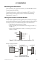
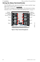
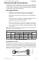
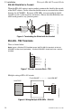
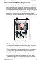
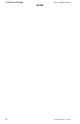
Table Of Contents
- 1. Introduction
- 2. Installation
- 3. Electrical Ratings
- Appendix A: MS-5210UD
- Appendix B: MS-9200
- Appendix C: MS-9600
Wiring the EIA-485 Terminal Blocks 2. Installation
ACM-8RF PN 50362:C 03/21/01
13
Wiring the EIA-485 Terminal Blocks
Communications between the Fire Alarm Control Panel and the ACM-8RF is
accomplished over a two-wire EIA-485 serial communications bus which must
be power-limited. Communications between the host FACP and ACM-8RFs
is supervised by the fire alarm control panel.
Wiring Specifications
• The EIA-485 circuit cannot be T-tapped; it must be wired in a
continuous fashion from the control panel to the ACM-8RFs.
• The maximum wiring distance between the panel and ACM-8RFs is
6,000 feet.
• The wiring must be a 18 AWG to 14 AWG twisted shielded pair cable
having a characteristic impedance of 120 ohms, +/- 20%.
• Limit the total wire resistance to 100 ohms.
• Do not run cable adjacent to, or in the same conduit as, 120 volts AC
service, noisy electrical circuits that are powering mechanical bells or
horns, audio circuits above 25 V
RMS
, motor control circuits, or SCR
power circuits.
Note: Never use the EIA-485 shield for grounding purposes. Terminate the EIA-485
shield at the Fire Alarm Control Panel only.
Table 2 Wire Specifications
EIA-485 Shield in Conduit
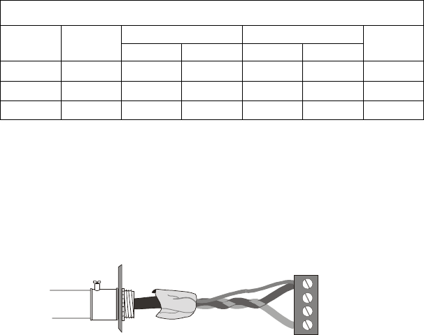
When the EIA-485 wiring is in conduit, connect the shield to system common.
The shield can enter the cabinet, but must be insulated from the cabinet (no
electrical contact). Between ACM-8RFs, wire-nut multiple shields together
(which can be inside of the respective ACM-8RF enclosure but ensure that the
shield does not contact earth ground).
Figure 5 Terminating the Shield in Conduit
Standard Annealed Copper Wire
Wire Size
A.W.G
Diameter
in Mils
Cross Section Ohms per 1000 feet
Pounds per
1000 feet
Circ. Mils Sq. Inch @ 77°F. @ 149°F.
14 64 4110 0.00323 2.85 2.97 12.4
16 51 2580 0.00203 4.09 4.73 7.82
18 40 1620 0.00128 6.51 7.51 4.92
1
IN (+)
4
IN (–)
TB2
3
OUT (–)
2
OUT (+)
ACM8RF-term1.cdr