
User Manual
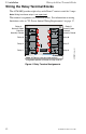
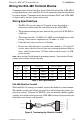
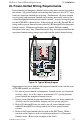


Table Of Contents
- 1. Introduction
- 2. Installation
- 3. Electrical Ratings
- Appendix A: MS-5210UD
- Appendix B: MS-9200
- Appendix C: MS-9600
UL Power-limited Wiring Requirements 2. Installation
ACM-8RF PN 50362:C 03/21/01
17
UL Power-limited Wiring Requirements
Power-limited and nonpower-limited circuit wiring must remain separated in
the cabinet. All power-limited circuit wiring must remain at least 0.25" away
from any nonpower-limited circuit wiring. Furthermore, all power-limited
circuit wiring and nonpower-limited circuit wiring must enter and exit the
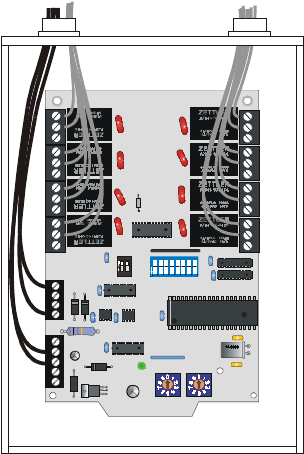
cabinet through different knockouts and/or conduits. A typical wiring diagram
for the ACM-8RF is shown below. In this diagram, relays K1 through K4 are
being used for power-limited circuits and relays K5 through K8 for nonpower-
limited circuits. Different applications may require different conduit
knockouts to be used. Any conduit knockouts may be used provided that the
nonpower-limited wiring remain separated from the power-limited wiring.
Figure 12 Typical Wiring Diagram
Requirements for power-limited and nonpower-limited circuits on the same
ACM-8RF module are as follows:
1. If a mix of power-limited and nonpower- limited circuits are connected
to relays, skip a set of dry contacts to maintain 0.25" spacing between
power-limited and nonpower-limited circuits.
2. If only power-limited or nonpower-limited circuits are being employed,
all relays may be used without skipping any for spacing purposes.
3. Relays K1 through K4 may be used to run all power-limited circuits
while K5 through K8 are being used to run all non-power-limited
circuits.
4. Refer to the Power-limited label located on the FACP door. Make a
notation on the label for each circuit being employed as a Nonpower-
limited circuit. (Refer to the example on the label).
12
OFF
1
23456 78
O
F
F
K5
K6
K7
K8
K4
K3
K2
K1
ACM8RF-pwrltd.cdr