
User Manual
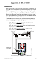

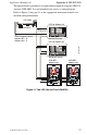
Table Of Contents
- 1. Introduction
- 2. Installation
- 3. Electrical Ratings
- Appendix A: MS-5210UD
- Appendix B: MS-9200
- Appendix C: MS-9600
Appendix A: MS-5210UD Application Example #4
30
ACM-8RF PN 50362:C 03/21/01
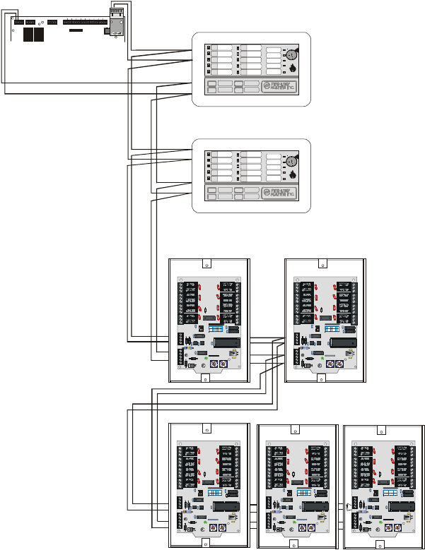
The figure below is provided as an application example of using two LED-10s
and two ACM-8RFs. It is not intended to be used as a wiring diagram.
Refer to Figure 13 on page 21, or the appropriate instruction manuals, for
detailed wiring information.
Figure 15 Two LED-10s and Five ACM-8RFs
J6
J6
+ - + -
+
+
-
-
FIRE ANNUNCIATOR
FIRE ANNUNCIATOR
12
OFF
12345678
O
F
F
12
OFF
1234 56 78
O
F
F
12
OFF
12 3456 78
O
F
F
12
OFF
12345678
O
F
F
12
OFF
12345678
O
F
F
FACP Program Level 3
Address 02 = ‘0’
Address 03 = ‘3’
LED-1 Address ‘01’
LED-1 Address ‘02’
Receive/Transmit
Receive/Transmit
LED-10IM
ACM-8RFs set to Address ‘03’ (Alarm Only)
ACM-8RFs set to Address ‘04’ (Alarm and Trouble)
Receive/Transmit
Receive/Transmit
Receive Only
Receive Only
Receive Only
acmfapp4.cdr