
User Manual
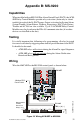
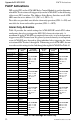
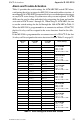
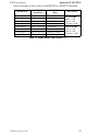
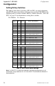
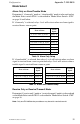
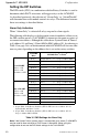
Table Of Contents
- 1. Introduction
- 2. Installation
- 3. Electrical Ratings
- Appendix A: MS-5210UD
- Appendix B: MS-9200
- Appendix C: MS-9600
Appendix C: MS-9600 Configuration
38
ACM-8RF PN 50362:C 03/21/01
Configuration
Setting Rotary Switches
The Address Select Rotary Switches (SW1 & SW2) are used to determine
which FACP annunciator address will trigger relays on the ACM-8RF. Use the
following table to set these switches. Refer to "Address Switches - SW1 and
SW2" on page 15 for information on setting these switches.
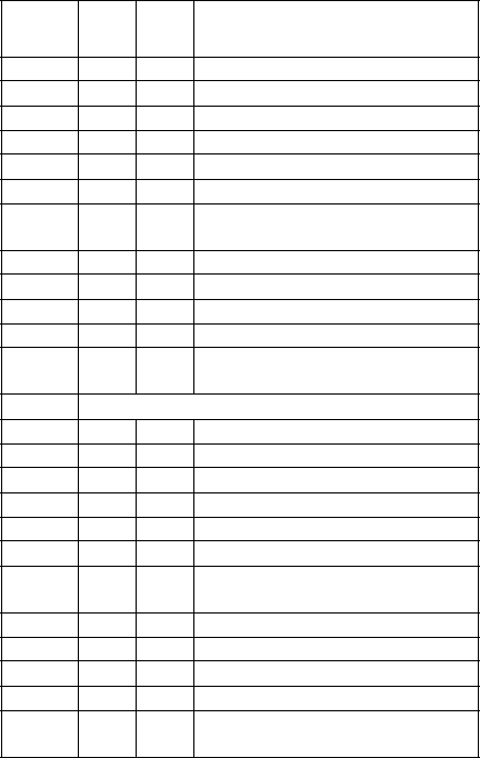
M = Module D = Detector
Table 13 SW1 & SW2 Switch Settings
Note: If a UDACT-F is installed and selected in control panel programming, it will
automatically assign addresses 20 - 31 to the UDACT-F and disable the selection of
these addresses.
FACP
Address
SW1 SW2 Relay Activation for:
1 0 1 8 System Points & Zones 1-56
2 0 2 Zones 57-99 & 2 NACs
3 0 3 Loop 1, Address M1 - M64
4 0 4 Loop 2, Address M1 - M64
5 0 5 Loop 1, Address M65 - M128
6 0 6 Loop 2, Address M65 - M128
707
Loop 1, Address M129 - M159 &
Loop 2, Address M129 - M159
8 0 8 Loop 1, Address D1 - D64
9 0 9 Loop 2, Address D1 - D64
10 1 0 Loop 1, Address D65 - D128
11 1 1 Loop 2, Address D65 - D128
12 1 2
Loop 1, Address D129 - D159 &
Loop 2, Address D129 - D159
13 - 19 Not Used
20 2 0 8 System Points & Zones 1-56
21 2 1 Zones 57-99 & 2 NACs
22 2 2 Loop 1, Address M1 - M64
23 2 3 Loop 2, Address M1 - M64
24 2 4 Loop 1, Address M65 - M128
25 2 5 Loop 2, Address M65 - M128
26 2 6
Loop 1, Address M129 - M159 &
Loop 2, Address M129 - M159
27 2 7 Loop 1, Address D1 - D64
28 2 8 Loop 2, Address D1 - D64
29 2 9 Loop 1, Address D65 - D128
30 3 0 Loop 2, Address D65 - D128
31 3 1
Loop 1, Address D129 - D159 &
Loop 2, Address D129 - D159