PN 50893:B ECN 00-317 Auxiliary Power Supply APS-6RF Instruction Manual Document 50893 07/20/2000 Rev: B
Fire Alarm System Limitations An automatic fire alarm system–typically made up of smoke detectors, heat detectors, manual pull stations, audible warning devices, and a fire alarm control with remote notification capability–can provide early warning of a developing fire. Such a system, however, does not assure protection against property damage or loss of life resulting from a fire.
Installation Precautions WARNING - Several different sources of power can be connected to the fire alarm control panel. Disconnect all sources of power before servicing. Control unit and associated equipment may be damaged by removing and/or inserting cards, modules, or interconnecting cables while the unit is energized. Do not attempt to install, service, or operate this unit until this manual is read and understood. CAUTION - System Reacceptance Test after Software Changes.
This Page Intentionally Left Blank 4 APS-6RF Instruction PN 50893:B 7/20/00
Table of Contents Table of Contents 1. Overview Introduction ..................................................................................................... 7 Description ....................................................................................................... 7 Specifications ................................................................................................... 9 2. Installation Introduction .................................................................................
This Page Intentionally Left Blank 6 APS-6RF Instruction PN 50893:B 7/20/00
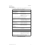
1. Overview Introduction This document contains information for installing, servicing, and configuring the APS-6RF Auxiliary Power Supply. The table below contains a list of document sources for supplemental information: Control Panels Refer to... Part Number Sensiscan 2000 Sensiscan 2000 Manual 15017 Sensiscan 200 Sensiscan 200 Manual 15032 All Firelite Device Compatibility Document 15384 Table 1 Supplemental Documentation Description APS-6Risoview.
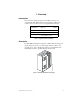
1. Overview Description The figures below identify the features of the APS-6RF power supply: Trouble In (J4) - Trouble Out (J3) “P” style connectors for internal cabinet connections Three 24 VDC output circuits Two (2) power-limited One (1) non power-limited Fuse F2 for battery protection (10A, 3AG, slow blow) APS-6Rsidebrd.
1. Overview Specifications Specifications The APS-6RF is compatible with the Sensiscan 2000, and Sensiscan 200 control panels. Specifications for the APS-6RF are: Electrical Specifications AC Primary Input Power Wire Size: #14 AWG with 600 VAC insulation 120 VAC, 60 Hz, 2.5 A 240 VAC, 50 Hz, 1.
NOTES 10 APS-6RF Instruction PN 50893:B 7/20/00
2. Installation ! WARNING: Use extreme caution when working with the APS-6RF. High voltage and AC line-connected circuits are present. Turn off and remove all power sources. To reduce the risk of electric shock make sure to properly ground the unit. Introduction This section contains instructions for common wiring, configuring and servicing the APS-6RF. For mounting and specific wiring instructions refer to the appendix concerning your system. Installation topics covered in detail: Topic Refer to...
2. Installation Wiring the APS-6RF Wiring the APS-6RF This section contains instructions for wiring the Auxiliary Power Supply as follows: • Typical field wiring from an APS-6RF to a control panel. • Wiring multiple APS-6RF power supplies. • Connecting an APS-6RF to an IC module Field Wiring an APS-6RF You can use J1 and J2 in place of TB2 when the APS-6RF is powering internal modules (such as an IC-4F, ICE-4F, TC-2F, TC-4F) with compatible connectors.
2. Installation Wiring the APS-6RF Connecting Multiple APS-6RF Power Supplies Typical trouble bus connections for multiple APS-6RF power supplies using trouble connectors J3 and J4. Use Cable 71033 or 75098 (same cables; different lengths) for all wiring. See appendix on your system for specific “Trouble Input” connection. Note: J3 and J4 can be interchanged.
2. Installation Wiring the APS-6RF Connecting the APS-6RF to an IC-4F/ICE-4F Module All four (4) NACs on the IC-4F are powered from the APS-6RF output circuit 2 (J2) and the four (4) NACs on the ICE-4F are powered from circuit 1 (J1). The NACs share the total 3A available from each circuit. Typical connections for wiring: J5 J 6 IC-4F J5 J 6 ICE-4F Blue Black Auxiliary Power Harness PN 71091 Blue Black J9 J1 J2 TB2 J3 APS-6RF APS-6Ricm.
2. Installation Configuring the APS-6RF Configuring the APS-6RF The APS-6RF may be configured for the following: • 8-hour delay for reporting loss of AC: cut jumper JP2. • 16-hour delay for reporting loss of AC: cut jumper JP2 and JP3. • 240 VAC operation: cut jumper JP1. J9 JP2 JP3 J2 TB2 J3 J1 The figure below illustrates the location of the jumpers: JP2 JP3 APS-6Rconfig.
2. Installation Servicing the APS-6RF Servicing the APS-6RF The only serviceable components on the APS-6RF are fuses F1 and F2. If a fuse fails, replace it with a fuse of the same type and rating: • F1 AC protection - 4A, 3 AG • F2 Battery protection - 10A, 3 AG To replace either fuse remove the vertical PC board as follows: 1. Turn off and remove all power sources. 2. Remove plastic cover. 3. Remove the two retaining screws securing vertical board. 4.
Appendix A: Sensiscan 200 Mounting in a CAB-200 Backbox The Auxiliary Power Supply is mounted as shown in the figure below. To mount the APS-6RF, follow these instructions: Step Action 1 Remove plastic cover from APS-6RF. 2 If 240 VAC is to be used, cut JP1 jumper at this time. See "Configuring the APS-6RF" on page 15. 3 Place the APS-6RF onto the mounting studs in the backbox.
Appendix A: Sensiscan 200 Connecting the APS-6RF to an MPS-24BF Connecting the APS-6RF to an MPS-24BF Make the following connections as shown in the figure below.
Appendix B: Sensiscan 2000 Mounting in CAB-A3F or CAB-B3F Cabinet This section contains instructions for the installation of the Auxiliary Power Supply onto a CHS-4F chassis used in a CAB-A3F or CAB-B3F cabinet. To mount the APS-6RF, follow these instructions: Action 1 Remove plastic cover from APS-6RF. 2 If 240 VAC is to be used, cut JP1 jumper at this time. See "Configuring the APS-6RF" on page 15. 3 Place the APS-6RF onto the mounting studs of the chassis.
Appendix B: Sensiscan 2000 Connecting the APS-6RF to an MPS-24AF Connecting the APS-6RF to an MPS-24AF Make the following connections as shown in the figure below.
Appendix B: Sensiscan 2000 Connecting the APS-6RF to an MPS-24BF Connecting the APS-6RF to an MPS-24BF Make the following connections as shown in the figure below.
NOTES 22 APS-6RF Instruction PN 50893:B 7/20/00
Index Index Numerics I 16-hour delay 15 240 VAC operation 15 use of 17, 19 8-hour delay 15 IC-4F/ICE-4F 12, 14 connections to 14 Installation topics 11 internal modules 12 J A AC protection J1 connection 12 J2 connection 12 J3 connection 13 J4 connection 13 JP1 jumper 15, 17, 19 JP2 jumper 15 JP3 jumper 15 jumpers, location of 15 16 B backbox 17 Battery protection 16 C CAB-200 17 CAB-A3F/-B3F cabinets 19 cable 13 chassis mounting 19 CHS-4F 19 configuring 15 connections MPS-24A 20 MPS-24B 21 MPS-24
Index serviceable components Specifications 9 standoff 17, 19 16 T TB2 12 TC-2F/TC-4F 12 terminal block cover 12 Trouble Bus 12 trouble connectors 13 trouble input 18, 20, 21 W Warning, High Voltage 11 wiring 12 24 APS-6RF Instruction PN 50893:B 7/20/00
APS-6RF Instruction PN 50893:B 7/20/00 25
APS-6RF Instruction PN 50893:B 7/20/00
Limited Warranty The manufacturer warrants its products to be free from defects in materials and workmanship for eighteen (18) months from the date of manufacture, under normal use and service. Products are date-stamped at time of manufacture. The sole and exclusive obligation of the manufacturer is to repair or replace, at its option, free of charge for parts and labor, any part which is defective in materials or workmanship under normal use and service.
World Headquarters One Fire-Lite Place, Northford, CT 06472-1653 USA 203-484-7161 • Fax 203-484-7118 www.firelite.