
User Manual


Specifications 1. Overview
APS-6RF Instruction PN 50893:B 7/20/00
9
Specifications
The APS-6RF is compatible with the Sensiscan 2000, and Sensiscan 200
control panels. Specifications for the APS-6RF are:
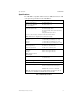
Table 2 APS-6RF Specifications
Electrical Specifications
AC Primary Input Power
Wire Size: #14 AWG with
600 VAC insulation
120 VAC, 60 Hz, 2.5 A
240 VAC, 50 Hz, 1.2 A
24 VDC Secondary Input Power
(lead-acid batteries only)
Current draw with AC power loss
25 mA DC standby current
16 mA DC standby current (with AC fail delay
operating)
6 amps maximum alarm current
Use these values in battery calculations for Fire Alarm Control Panel
Note: Batteries are charged by the system power supply.
24 VDC output power
Circuit 1
Circuit 2
Circuit 3
Total 6 A (4 A continuous)
3 A @24 VDC power-limited (+10, –15%)
3 A @24 VDC power-limited (+10, –15%)
6 A @24 VDC non power-limited (+10, –15%)
Fuses
F1 (AC supervision)
F2 (battery supervision)
250 VAC, 4A, 3 AG, slow blow
32 VAC, 10 A, 3 AG, slow blow
Trouble supervision bus
J3 output
J4 input
Note: J3 and J4 can be
interchanged.
Form A contact (open collector)
Form A contact (open collector)
Loss of AC Indication Immediate indication (default)
8 or 16 hour delay
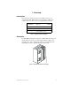
Mechanical Specifications
Size of APS-6RF in enclosure 6.09 in. x 4.23 in. x 2.92 in.
Cabinets for mounting CAB-A3F or CAB-B3F, using CHS-4F
chassis, for Sensiscan 2000 control panel.
Sensiscan 200 can mount one APS-6RF.
Note: An optional module (such as an IC-4F) without an expansion card can
mount above an APS-6RF in a CHS-4F and a Sensiscan 200.