
User Manual

D450-15-00 1 I56-725-04
B524BI and B224BI Plug-in Isolator
Detector Bases
For use with the following smoke detectors:
In US: B524BI: 1551, 2551, 2551T, 5551, 5551R
B224BI: 1251, 2251, 3251
INSTALLATION AND MAINTENANCE INSTRUCTIONS
A Division of Pittway
3825 Ohio Avenue, St. Charles, Illinois 60174
1-800-SENSOR2, FAX: 630-377-6495
Before Installing
Please thoroughly read the system wiring and installation
manuals, and manual I56-407, Guide for Proper Use of Sys-
tem Smoke Detectors, which provides detailed information
on detector spacing, placement, zoning, and special appli-
cations. Copies of these manuals are available at no charge
from System Sensor.
NOTICE: This manual should be left with the owner/user
of this equipment.
IMPORTANT: The detectors used with these bases must be
tested and maintained following NFPA 72 requirements.
The detectors used with these bases should be cleaned at
least once a year.
General Information
Isolator bases prevent an entire communications loop from
being disabled when a short circuit occurs. They accom-
plish this by isolating that part of the loop containing the
Specifications
Base Diameter: 6.2 inches (157 mm)
Base Height
B224BI: 1.2 inches (31 mm)
B524BI: 1.4 inches (36 mm)
Mounting: 4-inch square box with or without plaster ring, Min. depth - 1.5 inches (13 mm)
4-inch octagon box, Min. depth - 1.5 inches (13 mm)
3-1/2-inch octagon box, Min. depth - 1.5 inches (13 mm)
Operating Temperature Range: –10°C to +60°C (14°F to 140°F)
NOTE: Do not install in locations where normal ambient temperature
extends beyond 0° to 49°C (32° to 120°F)
Operating Humidity Range: 10% to 93% Relative Humidity (Non-condensing)
Electrical Ratings
Operating Voltage: 15 to 28 VDC
Current
Standard: 450µA Maximum
Alarm: 5mA Maximum
short from the remainder of the circuit. These bases also
automatically restore the entire loop when the cause of the
short circuit is corrected. In general, up to 25 addressable
devices may be isolated between isolator bases. For the
purposes of determining the number of devices between
isolator bases, one 3251 is equivalent to 12 addressable de-
vices. For example, (13) 2251’s and (1) 3251 may be
grouped between two isolator bases.
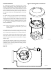
Mounting
The detector base mounts directly to 3
1
/2- and 4-inch octa-
gon and 4-inch square boxes, with or without a plaster
ring. To mount, remove the decorative ring by rotating it in
either direction to unhook the snaps. Then, separate the
ring from the base. Install the base on the box, using the
screws supplied with the junction box and the appropriate
slots in the base. Replace the decorative ring on the base
and rotate it in either direction until the ring snaps in place
(see Figure 1).