
User guide

D450-16-01 1 I56-659-06
B524RB(A) and B224RB(A) Plug-in
Relay Detector Bases
For use with the following models:
B524RB: For use with any 500 Series detector
B224RB: For use with any 200 Series detector
INSTALLATION AND MAINTENANCE INSTRUCTIONS
A Division of Pittway
3825 Ohio Avenue, St. Charles, Illinois 60174
1-800-SENSOR2, FAX: 630-377-6495
Before Installing
Please thoroughly read the system wiring and installation
manuals, and manual I56-407, Guide for Proper Use of Sys-
tem Smoke Detectors, which provides detailed information
on detector spacing, placement, zoning, and special appli-
cations. Copies of these manuals are available at no charge
from System Sensor. (For installation in Canada, refer to
CAN/ULC-S524, Standard for the Installation for Fire Alarm
Systems and CEC Part 1, Sec. 32.)
NOTICE: This manual should be left with the owner/user
of this equipment.
IMPORTANT: The detector used with these bases must be
tested and maintained regularly following NFPA 72 require-
ments. The detectors should be cleaned at least once a year.
Specifications
Base Diameter: 6.2 inches (157 mm)
Base Height
B224RB: 1.2 inches (31 mm)
B524RB: 1.4 inches (36 mm)
Mounting: 4-inch square box with or without plaster ring, Min Depth - 1.5 inches (13 mm)
4-inch octagon box, Min. depth - 1.5 inches (13 mm)
3
1
/2-inch octagon box, Min. depth - 1.5 inches (13 mm)
Operating Temperature Range: 0° to 49°C (32° to 120°F)
Operating Humidity Range: 10% to 93% Relative Humidity (Non-condensing)
Electrical Ratings
Operating Voltage: 15 to 28 VDC
Time Averaged Standby Ratings: <500
µ
A @ 24 VDC
Relay Characteristics
Coil: 2 coil latching
Contact Type: 1 Form C
Contact Relay
Resistive: 2 A @ 30 VDC
Inductive: 0.3 A @ 110 VDC (with .35 PF or greater)
0.3 A @ 120 VAC (with .35 PF or greater)
1.0 A @ 30 VDC (with .6 PF or greater)
Set Time: 4 seconds minimum, 20 seconds maximum
Reset Time: 1 second minimum, 8 seconds maximum
General Information
Form C latching relay contacts are included for the control
of an auxiliary function. The relay operates 12 seconds
(nominally) after activation of the sensor head remote an-
nunciator output.
Mounting
The detector base mounts directly to 3
1
/2- and 4-inch oc-
tagon and 4-inch square boxes, with or without a plaster
ring.
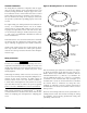
To mount, remove the decorative ring by rotating it in ei-
ther direction to unhook the snaps. Then, separate the ring
from the base. Install the base on the box, using the screws
supplied with the junction box and the appropriate slots in
the base. Replace the decorative ring on the base and ro-
tate it in either direction until the ring snaps in place (see
Figure 1).