
Manual

B350LP PLUG-IN DETECTOR BASE
INSTALLATION INSTRUCTIONS
Before installing detectors, please thoroughly read the system wiring and installation manuals, and manual I56-407,
Guide for Proper Use of System Smoke Detectors,
which provides detailed information on detector spacing, placement,
zoning, and special applications. Copies of these manuals are available from Fire•Lite.
GENERAL DESCRIPTION
The B350LP Plug-in Detector Base is used with Fire•Lite models CP350 ionization, SD350 and SD350T photoelectronic de-
tectors, and H350 and H350R heat detectors
The B350LP base is intended for use in a 2-wire addressable system, with screw terminals provided for power (+ and –),
and remote annunciator connections. Communication takes place over the power (+ and –) lines.
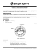
BASE TERMINALS
NO. FUNCTION
1 Power (–), Remote Annunciator (–)
2 Power (+)
3 Remote Annunciator (+)
A78-1318-00
F400-21-00 1 I56-954-01R
Fire•Lite Alarms, Inc., One Fire•Lite Place, Northford, CT 06472, 203-484-7161
Figure 1. Terminal Layout
SPECIFICATIONS
Diameter: 6.1 inches (155 mm)
Mounting: 4 inch (102 mm) square box with or without plaster ring
Min. Depth: 1.5 inches (38 mm)
4 inch Octagon Box, Min. Depth – 1.5 inches (38 mm)
3-1/2 inch Octagon Box, Min. Depth – 1.5 inches (38 mm)
Single Gang Box, Min. Depth – 1.5 inches (38 mm)
3
2
1
BASE
TERMINALS
TAMPER PROOF
TAB