
Manual

Document 51378 Revision A ECN 00-215 06/16/2000
12lobwiring.wmf
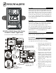
From FACP
IDC
To Next Device
IDC
Wiring Instructions
1) Surface mount the supplied Outdoor Backbox (WBB) using
the side flanges incorporate into the backbox design. The
box can be positioned to allow conduit connection from
any side. The pull station will mount in any position desired.
2) Before mounting the pull station, pull all necessary wiring
through the backbox.
3) Remove the correct amount of wire insulation. The pull
station’s backplate is molded with a strip gauge to measure
the amount of insulation to be removed.
4) Connect the wiring from the fire alarm control panel’s
Initiating Device Circuit (IDC), or any previous device on
the IDC to terminals 1 and 2 located on the pull station’s
terminal strip. Connect the next device on the IDC or End-
of-Line Resistor (ELR) to terminals 1 and 2.
Note: Maintain consistent polarity with all connections
throughout the IDC.
Outdoor Stations
Install the BG-12LO with a listed, outdoor-approved backbox
(WBB or WP-10) to meet UL requirements for outdoor use.
Without one of these backboxes, the BG-12LO is not listed for
outdoor applications. Use the four supplied 8-32 x .375"
mounting screws to attach the Pull Station to the outdoor-
approved backbox.
Operation
To activate the dual-action station, first push in the handle, and
then pull the handle down. The handle locks into the activated
position. The word ‘ACTIVATED’ appears after the handle is
pulled down. The pull station remains in the activated position
until reset with the key lock.
1) Reset the BG-12LOB by
inserting the key into the
lock and turning it ¼ turn
(counter-clockwise).
2) Open the door until the
handle returns to the
‘NORMAL’ position.
3) Close and lock the door.
Closing the door auto-
matically resets the switch
to the ‘NORMAL’ posi-
tion. Note: Opening the
pull station door will not
activate or deactivate the
FACP alarm switch.
CAUTION
Install the pull station in accordance with the supplied instructions, applicable NFPA standards, national and local Fire and Electrical
codes and the requirements of the Authority Having Jurisdiction (AHJ). Conduct regular testing of the devices using appropriate
NFPA standards. Fire•Lite is not responsible for devices that have not been properly installed, tested or maintained. For ADA
compliance, if the clear floor space only allows forward approach to an object, the maximum forward reach height allowed is 48 inches
(121.92cm). If the clear floor space allows parallel approach by a person in a wheelchair, the maximum side reach height allowed is
54 inches (137.16cm).
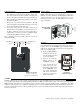
Outdoor-Use Gasket
(Does not cover any
user-serviced connections)
BG-12LO + WBB
= BG-12LOB
12LOBmount.wmf
BG12LOBact.wmf
BG-12LOB
Pull Station
(Shown Activated)