
Manual
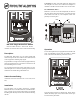

Resetting the Pull Station
1. Insert the key into the lock and rotate 1/4 turn coun-
terclockwise.
2. Open the door until the handle returns to normal.
3. Close and lock the door.
Note:
Closing the door automatically resets the switch to the ‘Nor-
mal’ position. Opening the door will not activate or deactivate the
alarm switch.
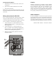
Wiring Instructions for BG-12SL
Prior to wiring the pull station, pull all necessary wiring
through a mounted backbox and the optional trim ring.
Connect the field wiring from the FACP’s IDC, or previous
device on the IDC, to the pull station’s pigtail wires.
1. Connect the positive (+) FACP’s IDC wire to a red
pigtail wire and the negative (–) FACP’s IDC wire to
a black pigtail wire.
2. Connect the positive (+) wire going to the next
device, or an ELR, to the remaining red pigtail wire
and the negative (–) wire going to the next device, or
an ELR, to the remaining black pigtail wire.
3. Maintain consistent polarity with all connections
throughout the IDC.
Caution
Install the pull station in accordance with the supplied
instructions, applicable NFPA standards, national and local
Fire and Electrical codes and the requirements of the
Authority Having Jurisdiction (AHJ). Conduct regular
testing of the devices using appropriate NFPA standards.
Fire•lite Alarms is not responsible for devices that have not
been properly installed, tested and maintained.
ADA Compliance
For ADA compliance, if the clear floor space only allows
forward approach to an object, the maximum forward reach
height allowed is 48-inches (121.92cm). If the clear floor
space allows parallel approach by a person in a wheelchair,
the maximum side reach allowed is 54-inches (137.16cm).
Document: 51860 Revision: A ECN: 01-500 09/14/01
RED
Positive
BLACK
Negative
BG12-wiring3.cdr