
Owner's manual


Installation and Configuration
Precautions
10 CHG-75 PN 51315:A 08/01/01
SECTION 2
Installation and Configuration
2.1 Precautions
Battery and Charger Precautions
When installing the CHG-75 battery charger, observe the following precautions:
❒
Do not
cut any jumpers when power is applied to the charger
❒
Observe polarity when making connections
❒
Do not connect the Battery Interconnect Cable until instructed
❒
Mounting batteries requires proper mounting hardware. Follow the battery
manufacturer’s installation instructions
❒
Be careful when lifting and handling batteries: batteries are heavy
❒
Batteries, although sealed, contain sulfuric acid which can cause severe burns to
the skin and eyes, and can destroy fabrics. If contact is made with sulfuric acid,
immediately flush the skin or eyes with water for 15 minutes and seek immediate
medical attention
❒
Charging batteries can cause flammable hydrogen gas
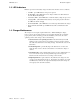
2.2 Charger Connections, Jumpers and Switches
The following figure illustrates all connections, jumpers and switches needed to
maintain, configure and operate the charger:
!
JP1
JP3
SW1
JP4
TB3
TB4
TB2
ENABLE
AC DELAY
16 HR
DELAY
TENS
ONES
CUT FOR
240VAC
GND FLT
DISABLE
AM-1 EN ABLE
ADDRESS
ON OFF
AM-1
JP5
JP2
F1
F2
J4
J1 J2
J3
F3
TB1
HOT
-
+
BATT
+
OUT TO FACP
-
EARTHNEUT
15
15
A- B- A+ B+
NC NO C
0
4
3
9
2
6
1
5
7
8
12
13
15
14
10
11
0
4
3
9
2
6
1
5
7
8
12
13
15
14
10
11
Figure 2.1 Charger Components
JP1 - In for 120VAC
Cut for 240VAC
Earth - TB1 Terminal 3
AC Neutral - TB1 Terminal 2
AC Hot - TB1 Terminal 1
(supervised)
SLC A- (TB3 Terminal 4)
SLC B- (TB3 Terminal 3)
SLC A+ (TB3 Terminal 2)
SLC B+ (TB3 Terminal 1)
(supervised & power-limited)
Relay*
Normally Closed (TB4 Terminal 3)
Normally Open (TB4 Terminal 2)
Common (TB4 Terminal 1)
J3 - Master Trouble In
J2 - Trouble Out
J1 - Trouble In
Low Battery - Yellow LED
Charging - Yellow LED
Trouble - Yellow LED
Ground Fault - Yellow LED
AC Power - Green LED
SLC Communication - Green LED
- Out to FACP (TB2 Terminal 4)
+ Out to FACP (TB2 Terminal 3)
- Battery, supervised (TB2 Terminal 2)
+ Battery, supervised (TB2 Terminal 1)
J4 Connector for AM-1 Ammeter
JP5 - Cut to Install AM-1
JP4 - Cut for 16 Hour AC Reporting Delay
JP3 - Cut for 8 or 16 Hour AC Reporting Delay
SW1 - On = SLC Communication Enabled
Off = SLC Communication Disabled
SLC Addressing Switches
SW2 Tens Switch
SW3 Ones Switch
CAUTION!
DO NOT
Cut any Jumpers
if power is applied!
JP2 - Cut to
Disable
Ground Fault
Detection
chg75brd.cdr
*Relay is fail-safe and contact
designations are shown with power
applied and no troubles on the charger.