0 Whitmore Road Woodbridge, Ontario L4L 7Z4 Phone (905) 856-8733 FAX (905) 856-9687 CMP-2401B/CMP-2402B Fire Alarm Control Panel Installation, Maintenance and Operating Instruction Manual Document 12/03/02 #50907 Rev.
Fire Alarm System Limitations While a fire alarm system may lower insurance rates, it is not a substitute for fire insurance! An automatic fire alarm system–typically made up of smoke detectors, heat detectors, manual pull stations, audible warning devices, and a fire alarm control with remote notification capability–can provide early warning of a developing fire. Such a system, however, does not assure protection against property damage or loss of life resulting from a fire.
Installation Precautions Adherence to the following will aid in problem-free installation with long-term reliability: WARNING - Several different sources of power can be connected to the fire alarm control panel. Disconnect all sources of power before servicing. Control unit and associated equipment may be damaged by removing and/or inserting cards, modules, or interconnecting cables while the unit is energized.
Notes 4 Document #50907 Rev.
Table of Contents CHAPTER 1: Product Description ......................................................................................................................... 9 1.1: Product Features ..........................................................................................................................................9 FIGURE 1-1: CMP-2401B/CMP-2402B.............................................................................................10 1.2: Specifications .............................
Notes 6 Document #50907 Rev.
This control panel has been designed to comply with standards set forth by the following regulatory agencies: • Underwriters Laboratories Standard UL 864 • NFPA 72 National Fire Alarm Code • CAN/ULC - S527M Standard for Control Units for Fire Alarm Systems Before proceeding, the installer should be familiar with the following documents.
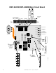
CMP-2401B/CMP-2402B Main Circuit Board + + + CMP-2402B Only Connections to Remote Trouble Buzzer GND AC TBL BUZ +24V ALARM REG RES NC C NO INITIAT ZONE 1 SIGNAL TROUBLE OUTPUT C NO + - - NC + INITIAT ZONE 2 - + TB1 TB2 GND AC TBL BUZ +24V ALARM REG RES NC C NO TB1 TROUBLE SIGNAL INITIAT OUTPUT ZONE 1 C NO + + NC - - INITIAT ZONE 2 - + SW1 SYSTEM RESET SW2 SIG SILENCE ZONE 1 SW3 SIG SILENCE ZONE 2 SW4 TBL SILENCE TB2 Transformer J5 System Reset Signal Silence Zone 1 Signal S
Product Description CHAPTER 1 Product Description The CMP-2401B is a one zone FACP (Fire Alarm Control Panel) and the CMP-2402B is a two zone FACP. This manual will use the term FACP to refer to both the CMP-2401B and CMP-2402B where features are identical. These control panels provide reliable fire signaling protection for small to medium sized commercial, industrial and institutional buildings.
Product Features FIGURE 1-1: CMP-2401B/CMP-2402B +24 Volt Resettable Power Remote Trouble Buzzer Input Zones (2 on CMP-2402B only) Trouble Relay Alarm Relay Cut if 4X Option Module is Installed Notification Appliance Circuit Transformer SIGNAL INITIAT TROUBLE GND AC TBL BUZ +24V ALARM OUTPUT ZONE 1 REG C NO RES NC C NO NC + + - - TB1 System Reset * INITIAT ZONE 2 - + SW2 SIG SILENCE ZONE 1 SW3 SIG SILENCE ZONE 2 SW4 TBL SILENCE J5 SW1 SYSTEM RESET TB2 CAUTION! HIGH VOLTAGE CUT IF
Specifications 1.2 Specifications AC Power - TB3 120 VAC, 60 Hz, 0.5 amps Fuse F2 - 2 Amp, 3AG Slow Blow Wire size: minimum #14 AWG (2.0 mm2) with 600V insulation Battery (lead acid only) - J3 Maximum Charging Circuit: Normal Flat Charge - 27.6V @ 0.8 amp Maximum Charger Capacity: 7.
Controls, Indicators and Operation 1.3 Controls, Indicators and Operation 1.3.1 Front Panel Slide Switches FIGURE 1-2: CMP-2401B/CMP-2402B Control Switches SIGNAL INITIAT OUTPUT ZONE 1 - + - + INITIAT ZONE 2 - + SW1 SYSTEM RESET SW2 SIG SILENCE ZONE 1 SW3 SIG SILENCE ZONE 2 SW4 TBL SILENCE TB2 System Reset Signal Silence Zone 1 Signal Silence Zone 2 (CMP-2402B only) Trouble Silence CUT IF 4X OPTION BOARD IS PRESENT 2402SWTC.
Controls, Indicators and Operation 1.3.2 LED Indicators FIGURE 1-3: LED Indicators (CMP-2402B Illustrated) 2401DISP.CDR The LED indicators for the CMP-2401B/CMP-2402B are labeled in English and French. The purpose of each indicator is listed below: AC Power (Alimentation) - green LED The green LED is on when the FACP is operating from normal AC power. The LED turns off to indicate a below normal AC voltage (brownout) or complete loss of AC power. The System Trouble LED will also turn on.
Controls, Indicators and Operation System Trouble (Trouble Systeme) - yellow LED This yellow LED turns on for all faults or abnormal operating conditions. Ground Fault (Faute M.A.L.T.) - yellow LED This yellow LED turns on to indicate a ground fault condition (low impedance to ground) on any field wiring or battery connections. 1.3.3 Local Sounder A piezo sounder provides distinct signals for alarm and trouble conditions: • Alarm - steady • Trouble - pulse 1.3.
Circuits 1.4 Circuits Input Circuits The CMP-2401B has one IDC (Initiating Device Circuit) and the CMP-2402B has two IDCs. Input circuit(s) provide Style B (Class B) configuration and accept 2-wire smoke detectors and normally-open contact devices. Output Circuits • 24 Volt Resettable Power Output 85 mA • 24 Volt Battery Charger (up to two 7 AH batteries) Notification Appliance Circuit One Style Y (Class B) Notification Appliance Circuit @ 1.
Optional Modules and Accessories 1.6 Optional Modules and Accessories 4XTMF Transmitter Module The 4XTMF Transmitter Module provides a supervised output for local energy municipal box transmitter and alarm and trouble reverse polarity. It includes a disable switch and disable trouble LED on the module. A jumper option on the module allows the reverse polarity circuit to open with a system trouble condition if no alarm condition exists.
Installation CHAPTER 2 2.1 Installation Mounting Options FIGURE 2-1: CMP-2401B/CMP-2402B Mounting The cabinet may be either semi-flush or surface mounted. The door is removable during the installation period by opening and lifting the door off the hinges. The cabinet mounts using two key slots and two additional 0.250” (0.635 cm) diameter holes located in the backbox. The key slots are located at the top of the backbox and the two securing holes at the bottom. 2.2 1. 2. 3. 4. 5. 6. 7. 8. MP2401DR.
Backbox Mounting Draw wires through the respective knockout locations. FIGURE 2-2: Cabinet Dimensions and Knockout Locations Top 1.125“ (2.858 cm) 10.125“ (25.718 cm) 8.125“ (20.638 cm) 6.125“ (15.558 cm) 4.125“ (10.478 cm) 0.875“ (2.223 cm) 1.25“ (3.175 cm) 3.000“ (7.620 cm) (7.62 cm) 3.0“ 1.25“ (3.175 cm) 12.5“ (31.75 cm) 6.5“ (16.51 cm) 1.000“ (2.540 cm) 3.25“ (8.255 cm) 1.75“ (4.445 cm) 16.625" (42.228 cm) 12.625" (32.068 cm) 9.500“ (24.130 cm) 14.625“ (37.148 cm) 14.5“ (36.83 cm) 3.
Backbox Mounting FIGURE 2-3: FACP Backbox Depth=3.000” (7.620 cm) Top Door=12.714" (32.294 cm) Backbox=12.5“ (31.75 cm) Door=14.714" (37.374 cm) Backbox=14.5" (36.83 cm) Right side 2401CABB.CDR Bottom Document #50907 Rev.
Operating Power 2.3 ! Operating Power WARNING: Several different sources of power can be connected to this panel. Disconnect all sources of power before servicing. The panel and associated equipment may be damaged by removing and/or inserting modules, interconnecting cables or wiring while this unit is energized. Primary Power Source (AC) and Earth Ground Connections AC power connections are made inside the control panel cabinet. The AC input circuit is limited by fuse F2 (2 amp, 3AG Slow Blow).
Input Circuits 2.4 Input Circuits The CMP-2401B has one IDC (Initiating Device Circuit) and the CMP-2402B has two IDCs. The maximum total loop resistance limit for each input circuit is 200 ohms. The field wiring is supervised for opens, shorts and ground faults. All conditions are visually and audibly annunciated. The zone(s) is a Style B (Class B) Initiating Device Circuit designed to accept any normally-open contact devices and conventional 2-wire or 4-wire, 24 VDC smoke detectors.
Output Circuits 2.5 Output Circuits DC Power Output Connections FIGURE 2-6: Auxiliary Power Connection 4-Wire Smoke Detector Power (85 mA) 24 VDC filtered, resettable power for 4-wire smoke detectors can be obtained from TB1 Terminals 24V Resettable (+) and Ground (-) GND AC TBL BUZ REMOTE + NC C NO NC C NO +24 VDC RESET ALARM TROUBLE - + - - + TB2 + SIGNAL INITIATING INITIATING OUTPUT ZONE 1 ZONE 2 2402TERM.
UL Power-limited Wiring Requirements Standard Relays The FACP provides two Form-C relays rated for 2.0 amps @ 30 VDC (resistive) and 2.0 amps @ 30 VAC (resistive). FIGURE 2-8: Relay Terminals Relay connections may be power-limited or nonpower-limited, provided that a minimum of 0.25" is maintained between conductors of power-limited and nonpower-limited circuits. ALARM TB1 GND AC TBL BUZ TROUBLE + NC C NO NC C NO - - + + - + TB2 2.6 M2401REL.
Installation of Optional Module 2.7 Installation of Optional Module CAUTION: Remove all power (AC and DC) before installing or removing modules or wiring. 2.7.1 4XTMF Transmitter Module Push the disconnect switch to the down position to prevent accidental activation of the municipal box during testing of the control panel. The Disconnect LED will remain illuminated while the municipal box is disconnected.
Installation of Optional Module 2.7.2 RTB - Remote Trouble Buzzer The RTB is a Remote Trouble Buzzer which provides a green AC Power LED and a yellow Trouble LED along with a piezo sounder, all of which mimic the condition of the control panel. The RTB can be mounted remotely in a single-gang electrical box. Four wires are required to connect the RTB to the CMP-2401B/CMP-2402B control panel as illustrated in Figure 2-11. FIGURE 2-11:RTB Remote Trouble Buzzer Connection RTB Remote Trouble Buzzer RTBBUZZ.
Programming Options CHAPTER 3 Programming Options This chapter describes the programming options available by cutting resistors on the FACP main circuit board. Options should be selected (resistors cut if necessary) prior to applying power to the control panel. 3.1 Earth Ground Fault Detection The FACP is factory configured to automatically detect ground fault conditions. A ground fault occurs when a low resistance is detected between an FACP circuit and earth ground.
Periodic Testing and Maintenance CHAPTER 4 Periodic Testing and Maintenance To ensure proper and reliable operation, it is recommended that system inspection and testing be scheduled monthly or as required by national and/or local fire codes. Testing should be done by a qualified service representative if a malfunction is encountered. Before Testing: 1. Notify the fire department and/or central alarm receiving station if an alarm condition will be transmitted. 2.
Battery Calculations Battery Calculations CHAPTER 5 Use the Total Standby and Alarm Load Currents calculated in Table 5-2 and Table 5-3 for the following battery calculation. TABLE 5-1: Battery Calculations Standby Load Current (amps) [ ] Alarm Load Current (amps) [ ] X Required Standby Time in Hours (24 or 60 Hours) [ ] = __________ X Required Alarm Time in Hours (i.e. 5 minutes = 0.084 10 minutes = 0.
The Main Power Supply 5.1 The Main Power Supply The FACP provides filtered power for operating the fire alarm control panel, external devices and the standby battery. The power for operating external devices is limited. Use Table 5-2 (standby or nonalarm) and Table 5-3 (alarm) to determine if external loading is within the capabilities of the power supply. For 4-wire smoke detectors, be sure to power them from TB1 Terminals (+24V Resettable) and (-Ground).
The Main Power Supply TABLE 5-3: Load in Alarm Current (amps) # of Devices Main Circuit Board 1 X 0.1251 = 4XTMF (1 max.) X 0.045 = Remote Trouble Unit (1 max.) X 0.050 = 4-wire Detector Heads2 [ ] X [ ] = Power Supervision Relays3 [ ] X [ ] = Notification Appliances4 [ ] X [ ] = Additional Current Draw from TB1 (nonalarm)2 = Sum Column for Alarm Load 1. 2. 3. 4.
Index Numerics 4XTMF see Transmitter Module M Maintenance 27 Mounting 17 A Alarm 14 N Notification Appliance Circuit 11, 15, 22 Current 11 End-of-Line Resistor 11 Style Y 11 Voltage 11 B Backbox 19 Battery 15 Alarm 30 Calculations 28 Charger 15 see also Power - Battery Standby 29 Trouble 13 O Operational Power 20 Primary 20 see Battery Output Circuits 22 Resettable Power 15 see’ Battery’ - ’Charger’ C Cabinet 15 Dimensions 18 Knockouts 18 see also Backbox P Piezo see Sounder Power AC 11 AC fuse 11 se
Notes 32 Document #50907 Rev.
Notes Document #50907 Rev.
Notes 34 Document #50907 Rev.
Limited Warranty The manufacturer warrants its products to be free from defects in materials and workmanship for eighteen (18) months from the date of manufacture, under normal use and service. Products are date-stamped at time of manufacture. The sole and exclusive obligation of the manufacturer is to repair or replace, at its option, free of charge for parts and labor, any part which is defective in materials or workmanship under normal use and service.
World Headquarters One Fire-Lite Place, Northford, CT 06472-1653 USA 203-484-7161 • Fax 203-484-7118 www.firelite.