
Owner's manual
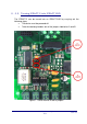
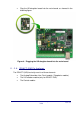
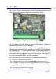
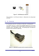
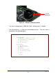
Table Of Contents

II - 2. LEDs
The IPDACT-2(UD) has three groups of LEDs that provide information on the
status of each type. These are displayed in the following figures:
Figure 10. LEDs and pins for an IPDACT-2(UD)
The LED labeled “ON” (LD1 for all the versions and releases) is green and
indicates that the IPDACT-2(UD) is powered.
Line status LED: Next to the relays there is a LED labeled LD6. In green this
indicates that the telephone relays are active i.e. the IPDACT-2(UD) intercepts
the telephone line. In normal working mode, this only occurs when the
IPDACT-2(UD) has connectivity with the configured VisorALARM. The relays
also activate when the telephone console activates (please see section IV.2
for further information). When the control panel is executing maintenance
tasks due to a bi-directional call, the relays are inactive.
LEDs LD2, LD3, LD4 and LD 5 each have an independent connotation:
• LED A LD2: Supervision information.
ON: a management frame is sent to the VisorALARM (contact or keep-alive).
OFF: a response is received to the sent management frame. If there is no response,
this remains active, indicating the lack of connectivity with the VisorALARM.
• LED B LD3: TO-AP terminal status
ON: the alarms panel telephone line is off hook.
OFF: the alarms panel telephone line is on hook.
IPDACT-2(UD) - Description
II-12
Doc.DM385-I
Rev. 4.0