
Owner's manual
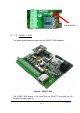
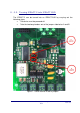
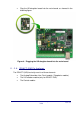
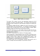
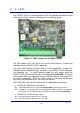
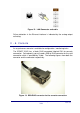
Table Of Contents

• LED C LD4: alarm sending to the VisorALARM.
ON: an alarm has been sent to the VisorALARM.
OFF: a response has been received to the sent alarm.
• LED D LD5: a bi-directional call to the alarm panel is in progress.
ON: there is a bi-directional call to the alarm panel. The LED located next to the
relays is off as the alarm panel has directly accessed the telephone line.
OFF: no bi-directional call in progress. The panel is operating normally.
II - 3. Jumper
The jumper labeled P1 operates by short-circuiting both pins with the supplied
berg header. This permits the following tasks:
a) On device startup this permits you to configure the IPDACT-2(UD) with
the default configuration. For further information on how to activate the
default configuration, please see section IV.2.1.1.
b) Keeping the P1 jumper short-circuited for a little more than a second
gives you access to the telephonic console. This permits you to
configure / monitor the IPDACT-2(UD) through a telephone connected to
the said IPDACT-2(UD). For further information, please see section
IV.2.
c) Keeping the berg header short-circuiting the P1 jumper denies access to
the serial console. You can regain access to the console by open-
circuiting the P1 jumper.
IPDACT-2(UD) - Description
II-13
Doc.DM385-I
Rev. 4.0
II - 4. Connection points to the Control Panel and
external
In order to connect the IPDACT-2(UD) to the control panel and to power this,
there is a row of connectors. All the connections are limited in power. As can
be seen in the following figure, the connections are grouped in the following
manner:
Figure 11. Connectors
Connectors to the control panel