
Manual


36 MS-2 & MS-4 Series Manual — P/N 51512:G2 10/18/2011
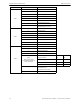
Program Options via DIP Switch DIP Switch Settings
IDC Combination Circuit
Switch 8, placed in the ON position, sets IDC #1 on the MS-2 or IDC #2 on the MS-4 as a combi-
nation circuit. A combination zone can be used for monitoring supervisory devices such as valve
tamper switches and alarm devices such as waterflow switches. Supervisory conditions, which
latch via software, can be silenced by pressing the Acknowledge and then Silence buttons. The fac-
tory default setting is switch 8 OFF for no Combination circuit.
3.1.2 SW2 DIP Switch Settings
IDC1 Verification (MS-4 only)
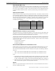
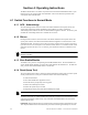
Switch 1 only on the MS-4, placed in the ON position, selects the Verification feature for IDC (Ini-
tiating Device Circuit) #1. When Verification is selected the following events will occur when a
smoke detector activates:
1. FACP removes power from all zones for 6 seconds, resetting all smoke detectors.
2. Power is reapplied and a 17 second retard period begins, allowing detectors to stabilize.
3. During the 23 second reset/retard periods of steps 1 & 2, subsequent alarms by the same zone
are ignored.
4. Alarms detected on any other zone during the retard period will cause the FACP to
immediately process the alarm.
5. A 60 second confirmation period follows the reset/retard period. If an alarm occurs during the
confirmation period, on the zone which initiated verification, the FACP will immediately
process the alarm. If no alarm is detected during this confirmation period, the FACP returns to
normal condition.
Important! Circuits selected for verification must have only smoke detectors installed
The factory default setting is switch 1 OFF for no IDC1 Verification.
IDC1 Supervisory (MS-4 only)
Switch 2 only on the MS-4, placed in the ON position, programs IDC #1 as a Supervisory circuit.
A supervisory zone can be used for monitoring supervisory devices such as sprinkler tamper
switches. A supervisory activation will pulse the piezo sounder at a ½ second rate and flash the
zone supervisory LED at the same rate. The factory default setting is switch 2 OFF for no IDC1
Supervisory.
IDC1 Verification for MS-2 or IDC2 Verification for MS-4
Switch 3, placed in the ON position, selects the Verification feature for IDC #1 on the MS-2 or IDC
#2 on the MS-4. The factory default setting is switch 3 OFF for no Verification. Refer to IDC1
Verification (MS-4 only) for a description of this feature.
83 sec.
23 sec.
0 sec.
CONFIRMATION
RETARD
Alarm Ignored
Control Panel Processes Alarm if Same Detector is Still in Alarm
Control Panel Immediately Processes Alarm
Detector Alarm
Verification
(Reset/Retard +
Confirmation)
Detector Goes Into Alarm
Detector Alarms on Different
Zone During First Detector's
Verification Period
6 sec.
RESET