GETTING STARTED ECHELON diamond series BUILT-IN OUTDOOR GAS GRILL E660i, E790i, and E1060i INSTALLATION AND OWNER’S MANUAL INSTALLER: Leave these instructions with consumer. CONSUMER: Retain for future reference. E790i shown IMPORTANT: READ THESE INSTRUCTIONS CAREFULLY BEFORE STARTING INSTALLATION OR USE. WARNINGS AND SAFETY CODES WARNING: DANGER: IF YOU SMELL GAS: 1. 2. 3. 4. 1. Do not store or use gasoline or other flammable vapors and liquids in the vicinity of this or any other appliance. 2.
INSTALLATION INSTRUCTIONS ET MANUEL DU PROPRIÉTAIRE GRIL EXTÉRIEUR D’ÎLE DE GAZ D’ÉCHELON IMPORTANT: LISEZ CES INSTRUCTIONS SOIGNEUSEMENT AVANT DE COMMENCER L’INSTALLATION OU L’UTILISATION SÛRETÉ ET CODES D’AVERTISSEMENT DANGER: AVERTISSEMENT: SI VOUS SENTEZ LE GAZ : 1. Coupez le gaz à l’appareil. 2. Éteignez-vous n’importe quelle flamme nue. 3. Ouvrez le couvercle. 4. Si l’odeur continue, gardez loin de l’appareil et appelez immédiatement votre département de fournisseur ou de feu de gaz. 1.
CONTENTS GETTING STARTED INSTALLATION INSTALLATION �������������������������������������������������������� 21 INSTALLATION, OPERATION, AND SAFETY INFORMATION ������������������������������������������������������������4 COUNTER PREPARATION ������������������������������������� 21 SLIDE THE UNIT INTO THE ENCLOSURE CUTOUT 21 CONNECT THE GAS SUPPLY ��������������������������������� 22 LEAK TEST ���������������������������������������������������������� 22 INSTALL THE FLAVOR GRIDS ������������������������
INSTALLATION, OPERATION, AND SAFETY INFORMATION 1. The outdoor appliance and surrounding area MUST remain clear of flammable substances such as gasoline, yard debris, wood, etc. Maintain a minimum horizontal clearance of 18" (in all directions) from combustible materials/items. 2. Do not block the 1" front air inlet along the bottom of the control panel. See the COMBUSTION AIR AND COOLING AIRFLOW section under INSTALLATION REQUIREMENTS for details. 3.
GAS SAFETY INFORMATION WHEN OPERATING THIS GAS APPLIANCE, ALL INSTRUCTIONS AND WARNINGS MUST BE OBSERVED. FAILURE TO DO SO MAY RESULT IN A FIRE OR EXPLOSION CAUSING PROPERTY DAMAGE, BODILY INJURY, OR DEATH. WARNING This gas appliance, its enclosure, and the propane cylinder enclosure, if any, MUST be plumbed and vented in accordance with local building and safety codes and should be approved by local code enforcement officials.
UTILISATION SÛRE ET ENTRETIEN DES CYLINDRES DE GAZ DE PROPANE IMPORTANT POUR VOTRE SÛRETÉ LISEZ ET SUIVEZ TOUS LES AVERTISSEMENTS ÉQUIPÉS DE VOTRE CYLINDRE DE GAZ DE PROPANE. En actionnant cet appareil avec un cylindre de gaz de propane ON DOIT observer ces instructions et avertissements. LE MANQUE DE FAIRE AINSI PEUT AVOIR COMME CONSÉQUENCE UNE INCENDIE OU UNE EXPLOSION SÉRIEUSE.
SAFE USE & MAINTENANCE OF PROPANE GAS CYLINDERS IMPORTANT FOR YOUR SAFETY READ AND FOLLOW ALL WARNINGS PROVIDED WITH THE PROPANE-GAS CYLINDER. When operating this appliance with a propane-gas cylinder, these instructions and warnings MUST be observed. FAILURE TO DO SO MAY RESULT IN A SERIOUS FIRE OR EXPLOSION. CYLINDER/CONNECTOR REQUIREMENTS The use of pliers or a wrench should not be necessary. Only cylinders marked “propane” may be used. a.
GRILL ENCLOSURE / VENTILATION REQUIREMENTS Fire Magic GFRC islands are available. They meet all enclosure and ventilation requirements. For requirements regarding custom-built enclosures, see below. VE N TILATION (A LL E N C LOS U RE S ) When installing this unit in a combustible enclosure, an RHP insulating liner must be used. Reference Table 1 for liner model #. Ventilation Requirements: • Minimum 4 openings (2 per side wall - spaced at min.
GRILL ENCLOSURE / VENTILATION REQUIREMENTS (cont.) ENCLOSURE • The countertop MUST be constructed of noncombustible materials. The enclosure can be constructed of combustible or non-combustible materials. • Access to the interior of the enclosure is required for ease of installation and service. • For combustible enclosures, an insulating liner is always required (see Table 1). WHEN A PROPANE (L.P.) CYLINDER IS USED IN THE ENCLOSURE When a propane (L.P.
INSTALLATION REQUIREMENTS Installation must be performed by a qualified professional service technician. Combustible overhead construction: Exhaust hood required Non-combustible overhead construction: Exhaust hood highly recommended This unit is designed for outdoor use only. DO NOT use this unit inside a building, garage, or enclosed area. DO NOT use this unit in or on a recreational vehicle or boat.
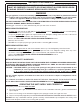
INSTALLATION REQUIREMENTS (Cont.) REAR WALL CLEARANCES Non-combustible For the minimum clearances between the unit and rear walls, your setup must fall within one (or more) of the following: Min. 4" A. Clearance between unit and strictly non-combustible rear wall (i.e. brick wall, see Fig. 11-1) • The unit must have a minimum clearance of 4" from the non-combustible rear wall. (To allow for proper ventilation and prevent dangerous overheating.) B.
INSTALLATION REQUIREMENTS (Cont.) CONTROL PANEL CLEARANCES • The control panel MUST have a minimum side clearance of 6" from any obstructions/side walls. See Fig. 12-1. (To allow for access to master switch and control panel removal.) • The control panel MUST remain removable for servicing (see CONTROL PANEL REMOVAL section). Any adjacent countertops must not obstruct the panel from being removed. Min. 6" Min. 6" COMBUSTION AIR AND COOLING AIRFLOW Proper airflow (front-to-back, Fig.
ELECTRICAL SAFETY • To protect against electric shock, do not immerse cord or plugs in water or other liquid. • Unplug from the outlet when not in use and before cleaning. Allow to cool before putting on or taking off parts. • Do not operate any outdoor cooking gas appliance with a damaged cord, plug, or after the appliance malfunctions or has been damaged in any manner. Contact the manufacturer for repair. • Do not let the cord hang over the edge of a table or touch hot surfaces.
MODEL SPECIFICATIONS Quantity Main burner N/P orifice drill size N/P air shutter opening † Back burner Infrared searing burner * E660i 3 #42 / #54 E790i 3 #38 / #53 E1060i 4 #40 / #53 3/8" 3/8" 3/8" / 1/2" / 1/2" / 1/2" Quantity 1 1 2 N/P orifice drill size #53 / #63 #51 / #57 #53 / #63 N/P orifice drill size #45 / #55 #45 / #55 #45 / #55 3176-52 3186-52 3185-52 23732-20 23745-20 23747-20 MK-1 MK-1 MK-1 MCK-1 MCK-1 MCK-1 Echelon insulating liner model # (not included)
MODEL SPECIFICATIONS (cont.) E660i 11 1/2" 31 1/4" 23 1/2" 33" A Countertop to unit bottom cutout* B Side to side non-combustible cutout* C Front to back non-combustible cutout*† D Control panel width non-combustible cutout‡ E790i 11 1/2" 37" 23 1/2" 38 3/4" E1060i 11 1/2" 50" 23 1/2" 51 3/4" * Note: If installing this grill in a combustible enclosure, the correct insulating liner must be used. Consult liner instructions for counter cutout dimensions and installation.
MODEL SPECIFICATIONS (cont.) SUBSTRATE When adding any substrate to the enclosure front wall (including tiles, stone, etc.), consider the following: Substrate Behind Control Panel Substrate Alongside Control Panel Substrate + countertop "front to back" cutout must equate to Dim. C (see previous page) when the substrate sits flush behind the control panel. Any additional substrate alongside the control panel does not need to be considered in Dim.
MODEL SPECIFICATIONS (cont.
ECHELON GRILL REPLACEMENT PARTS LIST 1 17 18 19 2 6 7 13 16 13 14 4 8 15 5 3 54 14 12 12 24 9 21 23 25 22 28 26 46 27 20 51 32 52 45 53 29 31 33 Items in light gray are not available on all models. Fig. 18-1 30 Some items shown are optional, or are n o t ava i l a bl e fo r certain models. Your model may vary, refer to parts list table. To order replacement par ts, contact your local Fire Magic® dealer.
ECHELON GRILL REPLACEMENT PARTS LIST (Cont.) E660i Item Description 1. Stainless cooking grid (set of 2 or 3) 2. Part No. E790i Qty. Part No. E1060i Qty. Part No. Qty. 3544-DS-3 1 3539-DS-3 1 23539-DS-2 2 Flavor grid (set of 3 or 4) 3070-S-3 1 3071-S-3 1 3071-S-4 1 3. Main burner 3041-50 3 3041-50 3 3041-50 4 4. Flame arrester kit 24177-05 3 24177-05 3 24177-05 4 5. Silicone gasket 24177-06 3 24177-06 3 24177-06 4 6.
ECHELON GRILL REPLACEMENT PARTS LIST (Cont.) E660i Item Description Part No. E790i Qty. Part No. E1060i Qty. Part No. Qty. 32. Drip tray 3087A 1 3087A 1 3087A 2 or Drip tray w/ match holder 3087M 1 3087M 1 3087M 2 33. Drip tray liner (set of 4) 3558 1 3558 1 3558 1 34. Wire harness w/ raceway ‡ 24194-49 1 24189-48 1 24184-48 1 35. Backburner electrode *‡ 4199-52 1 4199-52 1 4199-52 2 36. Main burner electrode ‡ 3199-72 3 3199-72 3 3199-72 4 37.
INSTALLATION INSTALLATION It is not required to remove the control panel or knobs to install this unit. DO NOT lift the unit from the control panel when installing. COUNTER PREPARATION CORRECT Consult Table 3 for non-combustible enclosure cutout dimensions. An RHP insulating liner must be used if any supporting construction is combustible. Consult the instructions that come with the liner for dimensions and additional installation information before beginning the installation.
INSTALLATION (cont.) CONNECT THE GAS SUPPLY To Connect To Propane Cylinder: Read the safety warnings and follow the instructions in the section SAFE USE AND MAINTENANCE OF PROPANE GAS CYLINDERS. Note: When a propane cylinder is installed inside of the enclosure, the guidelines found in the GRILL ENCLOSURE / VENTILATION REQUIREMENTS section MUST be followed. To Connect To Natural Or Household Propane Gas Supply: CAUTION: Use only C.S.A. listed stainless-steel flex connectors within the enclosure.
INSTALLATION (cont.) INSTALL THE FLAVOR GRIDS Place the flavor grids onto the front and rear flavor grid rests. Align the cutouts on the grids to the lighting tubes. See Fig. 23-1. The short grids are designed to rest over the outer burners and the tall grid(s) over the inside burner(s). The flavor grids allow heat from the burners to be evenly distributed throughout the cooking area. The tall side walls are designed to allow for maximum heat control and thermometer accuracy in each zone.
INSTALLATION (cont.) INSTALL THE DRIP TRAY Lift heatshield A Your grill includes a pack of four drip tray liners. 1. Lift the heatshield slightly, then place a liner into the drip tray (Fig. 24-1, A and B). 2. Then fully insert the drip tray assembly into the bottom front opening of the control panel (Fig. 24-1, C). INSTALL THE WARMING RACK C B Note: Wear heat-resistant gloves if necessary. Install liner 1.
ELECTRICAL INSTALLATION POWER SUPPLY The electrical connections from the power supply box to the unit come pre-connected. If side cookers are to be installed and will be powered using the same grill power supply, instead refer to the POWER SUPPLY / WIRE HARNESS CONNECTIONS section of the owner's manual included with the side cooker for power supply installation. CAUTION: IMPROPERLY CONNECTED WIRES WILL CAUSE DAMAGE TO THE UNIT AND MAY RESULT IN PROPERTY DAMAGE AND/OR PERSONAL INJURY.
USE, CARE, & SERVICE IDENTIFICATION OF GRILL CONTROLS Control panel screw(s) Center right main burner control knob Right main burner control knob Right backburner control knob Left backburner control Left knob main burner control knob Meat probe Center left main burner control knob Drip trays Digital thermometer Master switch* * The master switch is push button operated and controls the power to all lights, igniters, and the thermometer.
BEFORE INITIAL USE USING THE GRILL Ensure that: • the unit has been properly installed and leak tested by a qualified professional service technician and as instructed in this manual. • you have read and understand all of the information in this manual. BEFORE EACH USE Ensure that: • you smell around the appliance area for gas.
ALLUMAGE DES INSTRUCTIONS (D’ALLUMAGE) Lisez toutes les instructions avant l’allumage, et suivez ces instructions chaque fois vous lumière le unité. ÉCLAIRAGE ÉLECTRONIQUE ÉCLAIRAGE ÉCLAIRAGE MANUEL MANUEL Note: RRN O SUTU TO Le unité doitélectronique être relié à la puissance 120VAC pour L’éclairage exige une batterie installée ATTENTION: ATTENTION: Attendez Attendez toujours toujours cinq cinq (5) (5) minutes minutes le le gaz gaz l’éclairage électronique. de 9 volts avec une bonne charge.
LIGHTING (IGNITION) INSTRUCTIONS Read all instructions before lighting, and follow these instructions each time you light the unit. ELECTRONIC LIGHTING MANUAL LIGHTING Note: Electronic lighting requires an installedpower 9-volt This unit must be connected to 120VAC battery with alighting. good charge. for electronic Openlid(s) lid(s)or orremove removecover(s) cover(s) from from burner(s) burner(s) to to be 1.1. Open be lit. lit.
DIGITAL THERMOMETER / INTERIOR OVEN LIGHTS AND KNOB LIGHTS Your grill comes with a digital thermometer for temperature monitoring and timed cooking. Pressing any button will turn on the thermometer. The thermometer will automatically shut off after 5 minutes if no temperature change is detected. MEAT PROBE Note: The thermometer also controls the interior oven lights, and knob backlights. Thermometer shutdown will not shut off these lights; they must be manually shut off.
DIGITAL THERMOMETER / INTERIOR OVEN LIGHTS AND KNOB LIGHTS (Cont.) Setting a Zone and/or Meat Probe Temperature Current location 1. From default screen, press the down arrow to the desired zone / meat probe area (flashing). Press SET. 2. The selected location’s temperature screen will be displayed. Use the arrows to set the desired temp. The actual temp. will also be shown. See Fig. 31-1. Note: PRESSING the arrows will adjust the desired temp. by increments of one degree.
DIGITAL THERMOMETER / INTERIOR OVEN LIGHTS AND KNOB LIGHTS (Cont.) Setting the Alarm (Zones or Meat Probe) Use arrows to select desired alarm The alarm can be individually set (ON or OFF) for the meat probe and each cooking zone. The default setting has the alarm OFF for the meat probe and cooking zones. The alarm always sounds for the TIMER. 1. Under the menu screen select ALARM. Press SET. MENU 2. Use the up/down arrow to select the desired alarm, and press the light button to turn the alarm ON/OFF.
ROTISSERIE INSTRUCTIONS CAUTION: WHEN USING THE BACKBURNER; KEEP THE OVEN LID CLOSED TO PREVENT HEAT LOSS, PROVIDE PROPER CONVECTION, AND PROVIDE PROPER VENTING. THIS WILL ENSURE EVEN COOKING TEMPERATURES. Warming rack shown in storage position DO NOT KEEP YOUR OVEN LID OPEN DURING ROTISSING, AS THIS MAY CAUSE PERSONAL INJURY, OR IN SOME CASES, IN WINDY CONDITIONS, DAMAGE TO THE GRILL. DO NOT USE THE ROTISSERIE MOTOR IN THE RAIN. DO NOT LEAVE THE MOTOR ON THE GRILL WHEN NOT IN USE.
OPTIONAL INFRARED BURNER OPERATION The infrared searing burner (optional) cooks with a powerful radiant heat. Light the infrared burner following the LIGHTING INSTRUCTIONS found this manual or printed on the grill’s drip tray. When lighting manually, use the wire extension match holder included with this kit to safely hold a lit match. Follow these guidelines when operating the Infrared burner: Radiant protective screen • DO NOT place food on the cooking grid until the infrared burner glows orange (Fig.
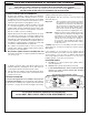
CHARCOAL/SMOKER BASKET (if equipped) CAUTION: Ensure grill is completely cool and knobs are in the OFF position. Note: This basket is designed for use over main burners only. DO NOT USE OVER INFRARED BURNERS. BASKET INSTALLATION 1. Place grid inside the basket frame (see Fig. 35-2). Smoker lid Grid/smoker lid lifter Expanded Stainless Steel Grid 2. Remove cooking grid and flavor grid from main burner where you wish to set basket. Note: Use the grid/smoker lid lifter (included) to remove cooking grid.
CHARCOAL/SMOKER BASKET (cont.) Observe all warnings supplied with your charcoal or wood chip/chunks. CHARCOAL COOKING DO NOT, under any circumstances, use quick-light charcoal. DO NOT use the smoker lid when cooking with charcoal. 1. Load charcoal onto the grid (see Fig. 36-1 and Fig. 36-2). • When loading charcoal, it MUST not be loaded more than 3/4" above top edge of basket frame walls (see Fig. 36-2). Fig. 36-1 Load charcoal into basket 2. Replace the cooking grid back onto the grill.
SERVICING AND CLEANING Your grill requires regular cleaning and maintenance. Refer to these instructions for details. Performing these procedures will ensure proper operation, appearance, and safety. WARNINGS • Prior to servicing or cleaning make sure the unit is completely cool, the control knobs are turned to the OFF position, the gas supply is shut off, the light switch is off, and the power supply is disconnected (as applicable and unless otherwise stated).
SERVICING AND CLEANING (cont.) For Environments High In Salt, Chloride, Or Other Corrosive Chemicals When this grill is installed in a corrosive environment such as near the ocean (salt air), poolside (chlorine and/or pool chemicals) or any other location with exposure to high salt/chloride content or corrosive chemicals/solutions, it will be more susceptible to corrosion and MUST be maintained/cleaned more frequently. • DO NOT store any corrosive chemicals (chlorine, hydrochloric acid, fertilizer, etc.
SERVICING AND CLEANING (Cont.) REPLACING HALOGEN BULBS 5. Wearing a pair of gloves, reach into the fixture, gently grab the bulb, and pull it straight out of the fixture so that the two pins at the base of the bulb come all the way out. Your grill is engineered with the conveniences of electrical power for illuminating and igniting the grill. To replace any interior oven light, follow the instructions below. Important: Bulb is halogen. DO NOT TOUCH with bare hands.
SERVICING AND CLEANING (Cont.) CONTROL PANEL REMOVAL 1. Turn the control knob(s) to the OFF position and turn off the gas supply to the unit. 2. Turn off the master switch and disconnect the power supply from the power source. Bezel removed 3. Pull the control knob(s) from the stems and set aside. 4. Slowly lift the lighted bezels to clear the valve stems, and let rest as shown in Fig. 40-1. 5. Remove the drip tray. Fig. 40-1 6.
SERVICING AND CLEANING (Cont.) MAIN BURNER REMOVAL 1. Remove the cooking grid and flavor grid from above the burner that is to be removed and set them aside. 2. Locate and remove the cotter pin from the left or right rear burner anchoring peg by pulling it straight out of the cotter pin hole using fingers or needle-nose pliers. See Fig. 41-1. 3. Carefully lift the burner from the burner support and out from the hole in the forward fire wall. See Fig. 41-2. Remove cotter pin 4.
SERVICING AND CLEANING (Cont.) POWER SUPPLY FUSE REPLACEMENT 1. Locate the power supply box inside of the island enclosure (reference the PARTS LIST). 2. Using a phillips screwdriver, remove the 4 large screws found on the cover of the power supply box (see Fig. 42-1). 3. Disconnect the power supply cord. Then disconnect the wire harness and ground wire (see Fig. 42-2). Completely remove the box from the enclosure for ease of fuse replacement. 4.
SERVICING AND CLEANING (Cont.) CONVERT GAS TYPE / CHECK BURNER ORIFICES CAUTION: Make sure the grill is at a safe temperature and isolated from gas and electrical supplies before beginning. For your safety, exercise caution, and make sure you have adequate hand protection, such as gloves, when handling metal parts. Apply Conversion Label This grill comes from the factory configured for one type of gas as marked on the label behind the control panel.
SERVICING AND CLEANING (Cont.) 3. Unfasten the two backburner nuts (found on the left side of the backburner) using a 1/4" nut driver and set them aside. See Fig. 44-2. 4. Remove the backburner by lifting the left side outward and to the left. See Fig. 44-3. 5. Use a 3/8" hex nut driver to remove the exposed orifice (Fig. 44-4). Check orifice. If needed, replace it with the correct orifice for the new gas. 6. Replace the backburner assembly and fasten the two nuts using a 1/4" nut driver. 7.
SERVICING AND CLEANING (Cont.) AIR SHUTTER ADJUSTMENT / BURNER FLAME INSPECTION Main Burner Flames: Important: Air shutters are preset at the factory (see Table 1 in MODEL SPECIFICATIONS). However, gas conversion, altitude, or other local conditions may make it necessary to adjust the air shutters. • blue • stable • quiet • touching burner Note: Infrared and backburner air shutters are not adjustable.
SERVICING AND CLEANING (Cont.) VALVE "LOW" SETTING ADJUSTMENT Stability of the "low" setting on main burners, and infrared burners may vary due to wind direction, grill configuration, and grill position. If your burner goes out when set on low, the valve "low" setting needs adjustment. Note: Adjustments MUST only be performed by a qualified professional service technician. Important: The valve "low" setting for the backburner must remain at the factory setting.
TROUBLESHOOTING If you have trouble with the unit, please use this list to identify the problem. By trying one or more of the solutions to the possible cause, you should be able to solve the problem. If this list does not cover your present problem, or if you have other technical difficulties with the unit, please contact your local dealer.
WARRANTY PETERSON FIRE MAGIC GRILLS AND ACCESSORIES LIMITED WARRANTY Robert H. Peterson Co. ("RHP") warrants your Fire Magic® grill to be free from defects in material and workmanship. Fire Magic® cast stainless-steel gas burners, Choice stainless steel U-shaped burners, cooking grids, and stainless steel housings are warranted as long as you own your Fire Magic® grill -- LIFETIME. (Except as described below.