
Instructions


6
REV 6 0906230824
L-C2-11109
2. CONNECTING THE GAS SUPPLY TO YOUR
FIRE MAGlC DOUBLE SIDEBURNER:
a. The valve manifold has a 1/2" male fl are
inlet fitting. A 1/2" female flare fitting
connector nut is required to hook the gas
supply to the double sideburner.
b. Use a stainless steel fl ex connector to bring
the gas supply from the gas line stub, or
propane gas tank to the double sideburner
manifold. A 1/2" x 24" or 36" fl ex connector
is suitable for most installations.
CAUTION: Use only a C.S.A. listed stainless
steel fl ex connector. Do not use
a rubber hose or plastic hose
within the enclosure for your
sideburner, it will leak, resulting
in an explosion and/or serious
injury.
c. Be sure the gas supply is OFF. Connect
the pipe adapter fi tting supplied with the
fl ex connector to the gas supply stub. Use
pipe joint compound that is resistant to all
gasses on the pipe fi tting. Tighten fi tting
to the gas supply and connector fl are nut
securely.
Note: Pipe joint compound should not be used
on fl are fi tting connections.
d. Slide the unit into the enclosure.
e. Connect the fl ex connector fl are nut to
the double sideburner manifold flare
fi tting. Be sure to tighten securely. Use a
second wrench to support the fi tting on the
manifold to avoid damaging the manifold.
f. Check all gas connections for leaks with
a brush and soapy water solution before
lighting. NEVER USE A MATCH OR
OPEN FLAME TO TEST FOR LEAKS.
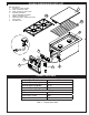
3. POSITIONING THE BURNER CAP:
Place the burner cap so it is centered over
the burner. Ensure that the notches in the
burner cap fi t over the studs protruding from
the burner (see Fig. 6-1).
INSTALLATION (Cont.)
The valve, igniter, and burner on your double sideburner have been pre-assembled and tested before
shipping. We suggest you follow and practice these instructions for safe lighting of your double sideburner.
Positioning
Each time you use your double sideburner, ensure
that:
1. The area around the unit is clear and free from
gasoline and other fl ammable vapors, liquids,
and materials.
2. There is no blockage of air fl ow around the
burner.
3. When using propane gas:
a. The special ventilation openings in the
enclosure are kept free and clear of debris.
b. If connected to a propane cylinder, the
rubber hose attached to the regulator is
carefully inspected before each use.
c. The propane cylinder, regulator, and rubber
hose are installed in a location not subject
to heating above 125° F (51° C).
4. Burner fl ames are burning evenly around the
burner cap with a steady fl ame (mostly blue
with yellow tipping).
Do not operate the burner with the cover
closed.
SAFETY TIPS FOR USING THE DOUBLE SIDEBURNER
f. If an orifi ce change is necessary, replace
the orifi ce with the correct sized one.
g. Replace the sideburner tube over the orifi ce,
aligning the burner over the electrode,
taking care not to detach it from the wire.
h. Replace the burner retaining clip (underneath
burner), and burner cap.
i. Repeat steps c. through h. for the second
burner, then replace the grid and lid.
Important: If converting the gas type, see the
CHECKING AND CONVERTING
THE REGULATOR section before
replacing the control panel.
i. Replace the control panel, being sure to
reconnect the battery holder assembly
wires. Replace the control knobs.
2. CONNECTING THE GAS SUPPLY TO YOUR
FIRE MAGlC SINGLE SIDEBURNER
a. The burner manifold has a
1
/
2
" male fl are
fi tting gas inlet elbow. A
1
/
2
" female fl are
fi tting connector nut is required to hook the
gas supply to the burner.
b. Use a stainless steel fl ex connector to bring
the gas supply from the gas line stub or
propane gas tank to the single sideburner
manifold. A
1
/
2
" x 24" or 36" fl ex connector
is suitable for most installations.
CAUTION: Use only a C.S.A. listed stainless
steel flex connector. Do not use
a rubber hose or plastic hose
within the enclosure for your single
sideburner; it will leak, resulting in
an explosion and/or serious injury.
c. Be sure the gas supply is OFF. Connect the
pipe adapter fi tting supplied with the fl ex
connector to the gas supply stub. Use pipe
joint compound that is resistant to all gasses
on the pipe fi tting. Tighten fi tting to the gas
supply and connector fl are nut securely.
Note: Pipe joint compound should not be
used on fl are fi tting connections.
d. Connect the flex connector flare nut to
the single sideburner manifold elbow fl are
fi tting. Be sure to tighten securely. Use a
second wrench to support the manifold to
avoid damaging the manifold.
e. Check all gas connections for leaks with
a brush and soapy water solution before
lighting. NEVER USE A MATCH OR OPEN
FLAME TO TEST FOR LEAKS.
f. Slide the unit into the enclosure.
3. POSITIONING THE BURNER CAP
Place the burner cap
so it is centered over
the burner. Ensure
that the notches in
the burner cap fi t over
the studs protruding
from the burner (see
Fig. 6-1).
Fig. 6-1