
Installation Instructions


10
REV 1 - 1108241141
L-C2-330
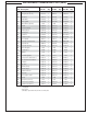
MODEL SPECIFICATIONS TABLE
Fire-Magic
®
Model Specifi cations Table
Table 1 E660s E790s E1060s
Main burner BTU (per burner)
N/P orifi ce drill size
25,000
#42/#54
32,000
#38/#53
28,000
#40/#53
Backburner BTU (per burner)
N/P orifi ce drill size
19,000
#49/#57
23,000
#44/#56
15,000
#51/#58
Single sideburner BTU
N/P orifi ce drill size
15,000
#50/#58
15,000
#50/#58
15,000
#50/#58
Double sideburner BTU (per burner)
N/P orifi ce drill size
15,000
#50/#58
15,000
#50/#58
15,000
#50/#58
Smoker drawer burner BTU
N/P orifi ce drill size
2,500
#68/#77
2,500
#68/#77
2,500
#68/#77
Infrared searing burner BTU (per burner)
N/P orifi ce drill size
24,000
#45/#55
24,000
#45/#55
24,000
#45/#55
Power burner BTU
Left N/P orifi ce drill size
Right N/P orifi ce drill size
- -
60,000
#30/#50
#46/#1.25
GFI Receptacle Rating 120V / 10 AMP Max
Oven Lights Rating 12V / 10 watt halogen bulb
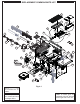
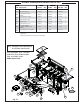
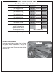
INSTALL ZONE DIVIDERS
Place the zone dividers as shown (Fig. 10-1) into
the grooves in the inner fi rewall of the grill to
allow for maximum heat control and thermometer
accuracy in each zone. Remove and store during
rotisserie use.
Fig. 10-1
Zone divider
Groove
Groove
Front