
Quick Start Guide

REV 2 - 1110241416
L-C2-336
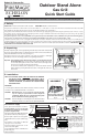
4-Grill Setup
Fig. 4-1
Cooking Grid
Flavor Grid
(not with IR)
Backburner
cover
Warming
rack
Cotter
Pin
Rotisserie
rod storage
ring
6-Propane Safety
Gas Cylinders
IMPORTANT: READ AND FOLLOW ALL WARNINGS PROVIDED WITH THE PROPANE-GAS CYLINDER.
READ ALL SAFETY INSTRUCTIONS AND WARNINGS REGARDING THE USE OF PROPANE GAS FOUND IN
YOUR OWNERS MANUAL.
Sideburner
lid
Parts Placement Checklist
Place the following items according to their position and orientation in
Fig. 4-1:
Flavor grids, cooking grids, heat zone dividers, backburner cover,
warming rack, meat probe.
Leave pre-installed E-burners in place to maintain proper alignment.
Backburner Cover
Hook the backburner cover over the top of the backburner to protect
the backburner from grease, dust and dirt when it is not in use. Remove
before use.
Warming Rack
The warming rack comes pre-installed. Remove zip ties before use.
Consult the owner’s manual to remove or replace.
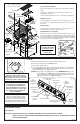
Shelf/Sideburner (if equipped)
Align the four (4) holes in the shelf with the four (4) holes in the side of
the cart while aligning and engaging the burner venturi with the orifi ce
(Fig. 4-2). Insert the four (4) screw (provided) into the holes and tighten.
Connect the spark wire to ignitor electrode (Fig. 4-2). Open sideburner
lid, set cap on burner, and set grid into shelf.
Screws
Ignitor
electrode
Air shutter
Orifi ce
Spark
wire
Fig. 4-2
Venturi
Note: For infrared burner equipped
grills; see detailed instructions
included in your owners manual.
Meat probe
Fig. 5-2
Left main burner
control knob
Right
main burner
control knob
Digital thermometer
Center right main burner
control knob
Center left main
burner
control knob
Smoker drawer
burner control
knob
Power hood control
switch (if equipped)
Right backburner
control knob
(if equipped)
Left
backburner
control knob
(if equipped)
Pull-out drip
tray
Meat probe
Wood chip
tray
Drip tray
liners
Drip tray (with
lighting instructions)
5-Test
1. Open the lid and remove any cover(s) of the burner(s) to be lit.
2. Turn all gas control knobs to the OFF position.
3. Turn the gas-supply valve on.
4. Depress the desired control knob, and while pressing turn it counterclockwise
to the HI LIGHT position. Once the burner lights, release the control knob.
(Repeat this step for each additional burner.)
CAUTION: If burner does not light within 5 seconds, IMMEDIATELY depress the
knob and turn it to the OFF position. Wait 5 minutes before repeating
step 4. If the burner does not light after repeated attempts, refer to the
Lighting Instructions in your Owners Manual.
Door
Drawers
Sideburner
control knob
WHEN OPERATING THIS
APPLIANCE WITH PROPANE, ALL
INSTRUCTIONS AND WARNINGS
MUST BE OBSERVED. FAILURE TO
DO SO MAY RESULT IN A FIRE OR
EXPLOSION CAUSING SERIOUS
INJURY OR DEATH.
The master switch (Fig. 5-2) controls
the power to all lights, igniters, and the
thermometer. It allows the power to be
turned on or off for safety and convenience.
The switch will need to be turned on prior to
each grill use, and turned off after each use.
For your convenience and safety;
when the control knob is in the
ON position, the gas fl ow indicator
will change from blue to red. (Red
indicates gas fl ow.) See Fig. 5-1.
Fig. 5-1 - Burner valve control knob
OFF
HI
LIGHT
LOW
TO
TURN OFF
T O TURN ON
Read setting
here
HIGH to
LIGHT
Read setting here
(OFF position shown)
To Turn OFF
To Turn ON
Use
HI (high)
to light
Press
knob in
to turn
Gas Flow
Indicator
Master
switch
E-burner
*
(comes pre-
installed)
*
The burner ports
and carry-over slots
must be kept clean to
ensure proper ignition
and operation.