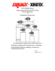
CG2 & MA2 Series Clean Agent FE-241 & HFC-227ea Owner’s Manual & Installation Instructions For all sizes 25 cubic feet to 1500 cubic feet Read and comply with all instructions, warnings and limitations before installing, servicing or removing this device. 1 18004 04/03/2007 Rev.
This owner’s manual and installation instructions pamphlet is provided in English. Additional copies in English are available at no charge by contacting the manufacturer, distributor or dealer. Copies in the language of destination are available upon request for an additional fee. Fireboy-Xintex reserves the right to change features without notice.
General Information Fireboy Automatic (CG series) and Manual/Automatic (MA) series Fire Extinguishing Systems are manufactured for a broad range of applications, including marine, industrial, and commercial uses. This booklet is intended to outline the proper installation of the system for marine applications; most applications are similar. If further technical advice is required, information is available by writing or calling Fireboy-Xintex.
• • • • • • • • WARNING: Never install a Fireboy system on the underside of a hatch cover or on an access door that may open or separate in an explosion Never install the actuator of a Fireboy system in close proximity to exhaust manifolds or turbochargers.
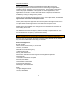
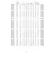
Volume Approximate Model Number CG2-550-FE241 CG2-600-FE241 CG2-650-FE241 CG2-700-FE241 CG2-750-FE241 CG2-800-FE241 CG2-850-FE241 CG2-900-FE241 CG2-950-FE241 CG2-1000-FE241 Protected ft^3 550 600 650 700 750 800 850 900 950 1000 m^3 15.6 17 18.4 19.8 21.2 22.6 24 25.5 26.9 28.3 Diameter in cm 7.2 18 7.2 18 7.2 18 10 25 10 25 10 25 10 25 10 25 10 25 10 25 Total Height in cm 24.7 63 24.7 63 24.7 63 21.6 55 21.6 55 21.6 55 21.6 55 21.6 55 21.6 55 21.6 55 Agent Weight lbs 18.6 20.3 22 23.7 25.4 27 28.
Volume Approximate Model Number CG2-300-227 CG2-325-227 CG2-350-227 CG2-375-227 CG2-400-227 CG2-450-227 CG2-500-227 CG2-550-227 CG2-600-227 CG2-650-227 CG2-700-227 CG2-750-227 CG2-800-227 CG2-850-227 CG2-900-227 CG2-950-227 CG2-1000-227 Protected ft^3 300 325 350 375 400 450 500 550 600 650 700 750 800 850 900 950 1000 m^3 8.5 9.2 10 10.6 11.3 12.7 14.1 15.6 17 18.4 19.8 21.2 22.6 24 25.5 26.9 28.3 Diameter in cm 7.2 18 7.2 18 7.
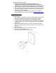
Marine Installation Instructions Before Installation 1. Check the system for damage during shipment. 2. Check the pressure gauge to be sure the gauge pointer lies within the green zone at 70°F (21°C). The correct weight is shown on the nameplate for the appropriate model. 3. Select an interior location not directly subject to weather or seawater. 4.
Accommodating Diesel Engines 1. Failure to install an Automatic Engine Shutdown in any compartment containing a diesel engine and a Fireboy system impedes the fire extinguisher and may prevent fire extinguishment. 2. Automatic Engine Shutdown units are available through your FireboyXintex distributor, dealer or retailer in three, five and eight circuit models. 3. Follow the installation instructions included with the Automatic Engine Shutdown for proper installation. 4.
• • • • WARNING: An electrical short may result in electrical burn, injury or fire Before attempting to wire the indicator lamp, turn off all electrical current to the ignition switch All Fireboy wiring must comply with the American Boat and Yacht Council Standard E9-9, titled Direct Current Electrical Systems for Boats, available from ABYC, 3069 Solomon’s Island Road, Edgewater, MD 21037 The indicator lamp supplied is for 12 VDC use only Wiring Instructions 1. Review all wiring instructions below. 2.
If the engine compartment is equipped with a powered ventilation system, U.S. Coast Guard Rule 162.029 requires that the ground connection of the ventilation system be connected to the Fireboy system. Failure to connect a powered ventilation system in the manner described below impedes fire extinguisher and may prevent fire extinguishment. Powered Ventilation Systems (Blowers) 1. Determine the maximum current draw of the powered ventilation system. 2.
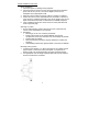
NOTE: Never push the cable at the T-handle end. Cable may jam and become inoperable. Fixing a jammed cable: 1. Turn the T-handle and threaded metal rod counter clockwise ½ turn until the jam releases. 2. If necessary, use a pair of pliers to carefully twist the threaded metal rod until the jam releases. 3. Pull the cable from the “S” hook until the cable returns to an operational position. 4. Do not connect cable to cylinder at this time. Routing the cable: 1.
6. 7. 8. 9. 10. 11. 12. 13. 14. 15. 16. 17. 18. 19. 20. Pull cable to full extension. Screw ferrule on to cable (approximately 4-5 turns maximum). Slide o-ring onto cable shaft. Screw red T-handle onto cable shaft (Do not obstruct cross hole in Thandle). Push red T-handle into ferrule to seat o-ring. Align holes in ferrule and T-handle. Temporarily install pull pin. Align T-handle so the word “FIRE” is vertical. Tighten the nut behind the panel. Recheck cable installation.
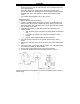
3. Push the cable end through the hole on the cylinder manifold far enough to allow the flexible strand to be bent. 4. Place “S” hook through the hole in the MA lever. 5. Gently pull cable sheath back into manifold, aligning the groove in sheath with slot in the manifold. 6. Insert the wire retaining clip provided around the groove in the cable sheath through the slot in the manifold securing the cable.
1. 2. 3. 4. A loud sound similar to small arms fire. A loud sound of rushing air. An extinguished indicator lamp. A stalled engine. When actuation occurs 1. Immediately shutdown all engines, powered ventilation, and electrical systems. 2. Extinguish all smoking materials. 3. Do not open the engine compartment. After actuation 1. Before inspecting for damage, allow the agent to “soak” the compartment for at least 15 minutes and wait for hot metals or fuels to cool. 2.
Inspect manual discharge cable annually when inspecting the fire extinguisher. 1. Do not remove the pull pin on the T-handle when disconnecting the manual discharge cable from the fire extinguisher manifold. 2. Remove the wire retaining clip securing the cable located at the slot in the top of the manifold. 3. Carefully push the cable from the backside of the manifold towards the actuator far enough to allow the flexible center strand to bend. 4. Remove the “S” hook from the black manual actuator lever. 5.
Automatic Engine Shutdown/Override System is required for use with Fireboy systems in diesel powered craft. Returning Fireboy-Xintex Equipment No product may be returned for credit or repair without a written “Returned Material Authorization” (RMA) form. Purchaser must call or email Fireboy-Xintex 616-735-9380 or fireboy@fireboy-xintex.com for a RMA. If due to extenuating circumstances a product is to be returned, after approval it must be received in 100% new/resalable condition.
NOTE: Detroit Diesel engines may require Automatic Engine Shutdown systems with time delay. Fireboy accessories are available from your Fireboy-Xintex distributor, dealer or retailer.
3 YEAR LIMITED WARRANTY This Warranty is in lieu of all other expressed of implied Warranties Seller warrants title, materials, and workmanship on equipment, except components manufactured by others for which the Seller assigns, as permitted, the original manufacturer’s warranty.