
Installation Sheet


42
CONTROL PANEL REMOVAL
1. Turn the control knob(s) to the OFF position and turn off the gas
supply to the unit.
2. Turn off the master switch and disconnect the power supply from the
power source.
3. Pull the control knob(s) from the stems and set aside .
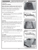
4. Slowly lift away the lighted bezels to clear the valve stems, and
carefully disconnect the wires found on the back of the bezels (use
your fi ngernail). See Fig. 42-1.
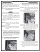
5. Remove the drip tray .
6. Using a Phillips screwdriver, unscrew and remove the control panel
fastener screws and washers (located on the left and right front face
of the control panel). Retain the screws for later re-installation .
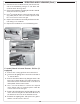
7. Carefully open the control panel by lifting and pulling the control panel
from the frame , allowing it to rest on the internal chain(s).
Important: When opening, take caution to not damage any wiring.
8. If wire disconnections are required, reference the wire diagram in the
MODEL SPECIFICATIONS section in this instruction manual or the
wire diagram label affi xed to the inside of the control panel.
Note: Secure any disconnected wires (coming from the inside of the unit) to prevent them from falling in.
Note: Whenever reconnecting any wires, apply a small amount of dielectric grease to the male connector,
then make the connection. This will ensure conductivity and prevent moisture from affecting the
contact.
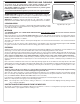
Important: To ensure the interior oven lights function: when reinstalling the control panel, set it
back over the front lip of the grill so that the light micro switch activation pin protrudes
through the hole on the upper right of the control panel (if applicable). See Fig. 42-2.
Important: During reinstallation; prior to opening the gas shut-off valve, be sure the control knob(s)
are in the OFF position.
Fig. 42-1
Bezel
installed
Bezel
removed
Carefully
disconnect
Fig. 42-2
Light micro switch
activation pin
(if equipped)
Must protrude through hole
(for lights to function)
SERVICING AND CLEANING (Cont.)