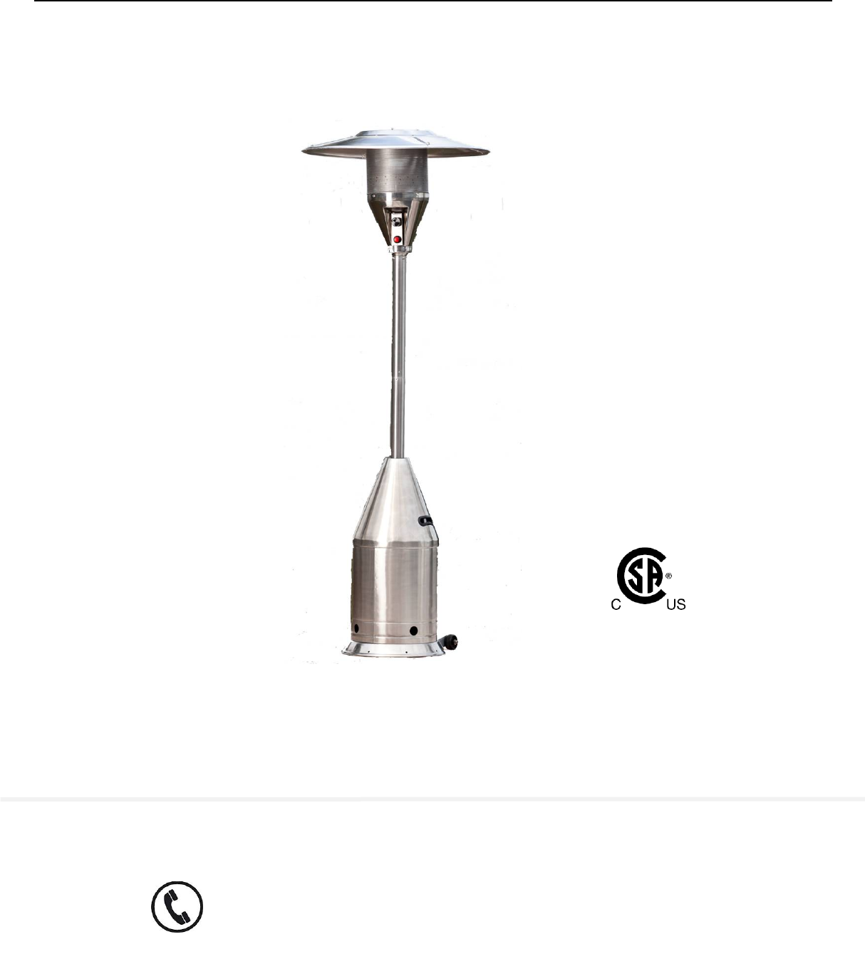
Outdoor Patio Heater Model # LIP-10A-TGG-LPG-BU Item # 61176,61186 ATTACH YOUR RECEIPT HERE Serial Number ___________ Purchase Date ______ Questions, problems, missing parts? Before returning to your retailer, call our customer service hotline at 1-866-985-7877, 9 a.m. – 6 p.m., EST, Monday – Friday or email at cservice@welltraveled.net.
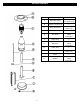
PACKAGE CONTENTS PART - 2- DESCRIPTION QTY 4 pcs (packed in 2 inner ctns) A Reflector Panel B Reflector Center Cap 1 C Head Assembly 1 (packed in 1 inner ctn) D Tank Housing 1 E Gas Hose 1 (attached to Head Assembly) F Upper Post 1 G Regulator 1 (packed with Head Assembly) H Lower Post 1 I Post Supports 3 (packed in 1 inner ctn) J Base 1 K Wheels 2 (packed with Head Assembly)
HARDWARE CONTENTS SAFETY INFORMATION SAFETY INFORMATION Please read and understand this entire manual before attempting to assemble, operate or install this appliance. If you have any questions regarding the product, please call customer service 1-866-985-7877, 9 a.m. – 6 p.m., EST, Monday – Friday. This manual contains important information about the assembly, operation and maintenance of this patio heater.
SAFETY INFORMATION - 4-
SAFETY INFORMATION ASSEMBLY PREPARATION Before beginning assembly of this appliance, make sure all parts are present. Compare all parts with package contents list and hardware contents as listed on pages 2 and 3 of this manual. If any part is missing or damaged, do not attempt to assemble this product. Contact customer service for replacement parts.
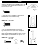
ASSEMBLY 1. Attach Wheels (K) to Base (J). Align holes in Wheel bracket with corresponding holes in Base, and insert 3 M6x16 (BB) bolts through holes and finger tighten. Repeat with second wheel. Tighten with wrench once both wheels have been attached. 1 Hardware Used: 6 x BB, Bolt M6x16 2. Attach the Post Supports (I) to the Base (J). Align the holes in the bottom of each Post Support with the hole on the Base. Insert 1 M8x16 (AA) bolt through the hole in the support and into the Base and hand tighten.
ASSEMBLY 4. Attach Upper Post (F) to Lower Post (H) by screwing the two pieces of the post together. 5. Place Tank Housing (D) onto Base (J). Slide Tank Housing (D) over the assembled Upper/Lower Post and down over the Post Supports. Rest Tank Housing on Base. 6. Attach Head Assembly (C) to Upper Post (F). Note: There is a small piece of protective foam located in the neck of the Head Assembly that MUST be removed prior to attaching Head Assembly to the Upper Post.
ASSEMBLY 7. Assemble Reflector Panels (A) with Reflector Center Cap (B).Reflector Panels (A) come packaged in two brown boxes with two panels in each box. Hardware for assembly is already affixed to each panel. Place two panels side by side and remove the two cap nuts and washers that are affixed to one panel. Insert the affixed bolts into the open holes on the adjacent panel. Place the washer over the bolt and screw on cap nut. Repeat these steps until all four panels are assembled.
ASSEMBLY A minimum supply pressure of .5 psi is required for the purpose of input adjustment of propane gas. Storage of an appliance indoors is permissible only if the cylinder is disconnected and removed from the appliance. A cylinder must be stored outdoors in a well-ventilated area out of the reach of children. A disconnected cylinder must have dust caps tightly installed and must not be stored in a building, garage, or any other enclosed area. The minimum permissible gas supply pressure of 11 W.C.
OPERATING INSTRUCTIONS 3. If leak is detected at regulator/cylinder valve connection, disconnect, reconnect, and perform another leak check. If you continue to see bubbles after several attempts, cylinder valve is defective. Call our customer service hotline at 1-866-985-7877, 9 a.m. – 6 p.m., EST, Monday – Friday IF NO BUBBLES APPEAR AT ANY CONNECTION, THE CONNECTIONS ARE SECURE. Note: Whenever gas connections are loosened or removed, you must perform a complete leak check.
OPERATING INSTRUCTIONS When Heater is ON: Emitter screen will become bright red due to intense heat. The color is more visible at night. Burner will display tongues of blue and yellow flame. These flames should not be yellow or produce thick black smoke, indicating an obstruction of airflow through the burners. The flame should be blue with straight yellow tops. If excessive yellow flame is detected, turn off heater and consult “Troubleshooting” on page 13.
INSTRUCTIONS circulating air passageways of the heaterOPERATING be kept clean and free of debris and/or spider or insect nests. After Operation: 1. Gas control knob is in OFF position. 2. Gas tank valve is OFF. 3. Disconnect gas line. CARE AND MAINTENANCE To enjoy years of outstanding performance from your heater, make sure you perform the following maintenance activities on a regular basis: Keep exterior surfaces clean. 1. Use soapy water for cleaning. Never use flammable or corrosive cleaning agents. 2.
TROUBLESHOOTING If you have any questions regarding this product, please call our customer service hotline at 1-866-985-7877, 9a.m. – 6 p.m. (EST), Monday – Friday, or email us at cservice@welltraveled.net. PROBLEM Main burner will not light Low burner flame POSSIBLE CAUSE Turn gas valve ON Fuel tank may be empty Refill LPG tank Orifice blocked Clean or replace orifice Air in supply system Purge air from lines. Open gas lines and depress control knob for 2-3 mins.
Distributed By: Well Traveled Living 716 S 8th Street Amelia Island, FL 32034 Toll Free: 866-WTL-SUPP (866-985-7877) Web: www.wtliving.com Email: cservice@welltraveled.net 1 YEAR LIMITED WARRANTY – Customers in the Continental US All components are warranted for a period of 1 year after date of purchase by the original owner against defects in materials and workmanship under normal use.