
Installation Manual


2560
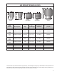
PARTS LIST
INSTALLATION INSTRUCTIONS
Congratulations — your new Air Helper Springs are
quality products capable of improving the handling and
comfort of your vehicle. As with all products, proper
installation is the key to obtaining all of the benets your
kit is capable of delivering. Please take a few minutes
to read through the instructions to identify the com-
ponents and learn where and how they are used. It
is a good idea to start by comparing the parts in your kit
with the parts list below.
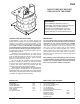
The heart of the air spring kit is, of course, the air
helper springs. Remember that the air helper springs
must ex and expand during operation, so be sure that
there is enough clearance to do so without rubbing
against any other part of the vehicle.
Be sure to take all applicable safety precautions
during the installation of the kit. The instructions listed
in this brochure and the illustrations all show the left,
or driver’s side of the vehicle. To install the right side
assembly simply follow the same procedures.
Your kit includes separate ination valves and air lines
for each air spring. This will allow you to compensate for
unbalanced loads. If you would rather have a single ination
valve system to provide equal pressure to both air springs,
your dealer can supply the optional “T” tting.
IMPORTANT!
For your safety and to prevent possible damage to
your vehicle, do not exceed the maximum load rec-
ommended by the vehicle manufacturer (GVWR).
Although your Air Helper Springs are rated at a maxi-
mum ination pressure of 100 psi, this pressure may
allow you to carry too great a load on some vehicles.
It is best to have your vehicle weighed once it is com-
pletely loaded and compare that weight to the maxi-
mum allowed. Check your vehicle owner’s manual or
data plate on driver side door for maximum loads listed
for your vehicle.
When inating your Air Helper Springs, add air pressure
in small quantities, checking pressure frequently during
ination. The air spring requires much less air volume
than a tire and, therefore, inates much quicker.
AIR SPRING 6401 2
UPPER BRACKET 5740 2
LOWER BRACKET 5370 2
AXLE CLAMP BRACKET 5181 2
HEAT SHIELD 1004 1
22 FT. TUBING 1
3/8"-16 BAIL CLAMP 3292 2
1-13
5/16" FLAT WASHER 4
3/8"-16 X 3/4" FLANGE BOLT 2
3/8"-16 FLANGE NUT 4
3/4"-16 HEX NUT 2
3/4" STAR WASHER 2
10MM X 30MM FLAT HEAD BOLT 4
INFLATION VALVE 3032 2
ELBOW FITTING 3031 2
THERMAL SLEEVE 0899 2
NYLON TIE WRAP 6
CAUTION TAG 2
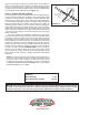
THIS KIT DOES NOT REQUIRE
DRILLING INTO THE FRAME.
BOLT PACK (A21-760-2560)
WARNING:
Do not inate this assembly when it is
unrestricted. The assembly must be restricted
by the suspension or other adequate
structure. Do not inate beyond 100 psi.
Improper use or over ination may cause
property damage or severe personal injury.