
Installation Manual


NOTE:
Please read thorough this manual completely before installing the air
spring kit on your vehicle.
STEP 1 — PREPARE THE VEHICLE
With the vehicle on a solid, level surface chock the front wheels.
Remove the negative battery cable. Your vehicle is equipped with
rubber jounce bumpers. The jounce bumpers are bolted to the frame
above the axle. Remove the jounce bumpers from the vehicle.
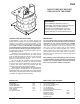
STEP 2 — PRE-ASSEMBLE THE KIT
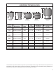
Select a lower bracket from your kit and determine which side of the
bracket ts most snugly between the axle U-bolts as shown in Figure
“A”. NOTE: The smaller side is for the gasoline engine axle and
the larger side is for Diesel engine axle. Select one air spring, bail
clamp and lower bracket from your kit. Place the bail clamp in the
correct position in the slot of the lower bracket for your vehicle. Install
the air spring to the lower bracket using the hole for your vehicle with
a 3/8"-16 x 3/4" ange head bolt that is mounted nger tight. Please
see the lower right section of Figure “A”. The bolt will be tightened
up in STEP 5.
STEP 3 — INSTALLING THE UPPER BRACKET TO THE
VEHICLE
Select an upper bracket and upper brace from your kit. Install the
upper bracket to the frame using two 10 mm x 30 mm at head bolts,
see Figure “A”.
STEP 4—INSTALLING THE ASSEMBLY TO THE VEHICLE
Position the lower bracket and air spring assembly from STEP 2 on
the axle as shown in Figure “A”. Put the large threaded stud though
the large hole on the upper bracket and the locating pin of the air
spring in the small hole on the upper bracket as shown in Figure “A”.
Make sure the aliment pin is in the locating hole before fasting
air spring to the upper bracket. Fasten the air spring to the upper
bracket using ¾"-16 hex head nut and ¾" star washer. Fasten the
lower bracket to the axle housing using the bail clamp and the axle
clamp bracket and two 3/8"-16 locking ange nuts securely. Once the
lower bracket orientation has been set, tighten the 3/8"-16 x ¾" ange
bolt that was installed in STEP 2. Next, install the male air tting into
the air inlet in the combo stud of the air spring. Tighten the air tting
securely to engage the orange thread sealant.
STEP 5— INSTALLATION OF THE PASSENGER’S SIDE
ASSEMBLY
Before following STEPS 1-4 with reverse orientations for assembly
and installation of the passenger’s assembly, a heat shield will need
to be mounted between the upper bracket assembly and the top plate
of the air spring, see Figure “C”. Position the heat shield directly
between the closest heat source and the air spring. Ensure that the
heat shield will not interfere with normal operation of the air spring
or the vehicle’s suspension. Do not position the heat shield directly
above the axle, as it may contact the axle on full suspension travel.
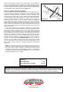
STEP 6 — INSTALL THE AIRLINE AND INFLATION VALVE
Uncoil the airline tubing and cut it into two equal lengths. DO NOT
FOLD OR KINK THE AIRLINE TUBING. Try to make the cut as
square as possible. Insert one end of the airline tubing into the air t-
ting installed in the top of the air helper spring. Push the airline tubing
into the tting as far as possible, see Figure “A”.
Select a location on the vehicle for the air ination valves. The
location can be on the bumper or the body of the vehicle, as long
as it is in a protected location so the valve will not be damaged, but
maintain accessibility for the air chuck, see Figure “D”. Drill a 5/16"
hole and install the air ination valve using two 5/16" at washers per
valve as supports, see Figure “E”. Run the airline tubing from the
air helper spring to the valve, routing it to avoid direct heat from the
FIGURE “C”
FIGURE “D”
(Step 5)
(Step 6)