TABLE OF CONTENTS WARRANTY . . . . . . . . . . . . . . . . . . . . . . . . . . . . . . . . . . . . . . . . . . . . . . . . . . . . . . . . . .i LIMITATION OF LIABILITY . . . . . . . . . . . . . . . . . . . . . . . . . . . . . . . . . . . . . . . . . . . . . . . .i SYSTEM COMPONENTS . . . . . . . . . . . . . . . . . . . . . . . . . . . . . . . . . . . . . . . . . . . . . . . . .2 HEIGHT SENSOR INSTALLATION . . . . . . . . . . . . . . . . . . . . . . . . . . . . . . . . . . . . . . . . . . .
ongratulations on your purchase of a new IntelliRide system by Firestone. This kit will provide automatic height control and leveling of your vehicle. The following will introduce you to the system components as well as provide detailed instructions concerning installing the height sensors and programming the system. Be sure to take all applicable safety precautions during the installation of this kit. Position the vehicle on a solid level surface and apply the parking brake.
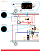
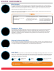
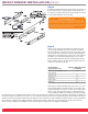
Figure 1 Connections to be made with vehicle interior Program button. This is disconnected after programming and replaced with the Park Wire. Grommet to be used if needed in the firewall. Height Control Switch Connector to ECU, to be mounted inside the vehicle. Battery Connection Compressor Relay To be mounted inside engine bay. Service Switch to be used to turn the system on and off. Ignition wire and ground wire. Ignition wire should be connected to a source less than 1/2 amp.
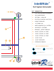
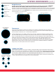
IntelliRide™ Full System Schematic DET DESCRIPTION 1 FULL SYSTEM VALVE ASSEMBLY 2 AIR COMPRESSOR 3 AIR TANK - 3 GALLON 4 ELECTRIC CONTROL UNIT (ECU) 5 HEIGHT SENSORS 6 1/4 TUBING 18ft.
SYSTEM COMPONENTS Wire Harness All necessary electrical wires and connectors have been included with this kit. Review Figure 1 before beginning installation. You will have to put the major components in a position so that the wire harness will reach all of them. Route the wire harness loosely throughout the vehicle as indicated in Figure 1. Each end of the wire harness is marked with the major component that it will connect with.
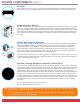
SYSTEM COMPONENTS (cont.) M5 Nylon Lock Nut (8) M5 x 8mm Machine Screw (8) M6 Nylon Lock Nut (4) Height Sensors The height sensor connections must go to their corresponding corners for proper sensor operation. THE HEIGHT SENSORS AND THE WIRE HARNESS CONNECTIONS ARE LOCATION AND POSITION SENSITIVE. The sensor connectors are laid out so they work with the sensors mounted on the outside of the frame rail, with the arms pointed toward the rear of the vehicle.
SYSTEM COMPONENTS (cont.) Air Dryer Select a location to mount the air dryer. This should be a protected location to prevent damage from flying rocks or debris and close to the valve block. Ensure that a clear access to all of the fittings on the air dryer is maintained. Height Selection Switch The height selection switch may be mounted directly in the dashboard, only if the dashboard material is 1/8” in thickness or less.
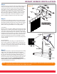
HEIGHT SENSOR INSTALLATION Step 1 There will be a bag in your kit with all of the hardware that you will need to put the height sensors on your vehicle. Group a height sensor from the kit with a height sensor bracket and two M5 x 8mm machine screws as indicated in Figure 2. Attach the bracket and height sensor template to the sensor using the machine screws, as shown in Figure 2. Next group a sensor arm and one M6 x 16mm and one M6 lock nut.
HEIGHT SENSOR INSTALLATION (cont.) Step 4 To install the height control sensor, refer to Figure 4a, 4b and 5, to become familiar with the mounting geometry and hardware. Be sure that the area above and below the sensor location on the axle is clear of obstructions for the arm to move.
HEIGHT SENSOR INSTALLATION (cont.) Step 6 Once the sensor positions have been found, mark the locations of the mounting holes on the vehicle frame using the holes in the height sensor bracket as a template, refer to Figure 3 and Figure 5. Use a center punch to mark the center of the holes on the mounting surface. Before drilling the holes make sure all electrical, brake and fuel lines are cleared from the path of the drill. Drill two 3/16” holes on the center marks.
PROGRAMMING THE SYSTEM For the system to operate properly the vehicle suspension travel will need to be programmed into the ECU. Reconnect the negative terminal on the battery. Raised Height Standard Height Lowered Height Step 1: Programming Setup Plug the program switch into the wire harness that is labeled program switch. Turn the system off using the service switch. When the system is off the side of the switch will be red.
OPERATION OF THE SYSTEM Once height programming has been completed, the system is ready for use. The height selection switch is how you will be able to select your height. The switch has two green lenses with arrows printed on them. This is the primary user interface of the air leveling system. If the switch is mounted correctly, pressing up will make the height go up and pressing down will make the height go down.
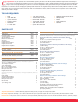
COMMONLY ASKED QUESTIONS What is the lifetime expectancy of the Firestone dryer? If there are no system leaks it should be for good for system life. What type of accuracy is available with our system? The height sensors that we use are capable of an accuracy of 0.67% of 1 degree. Our system with ECU programming is designed to work with 1/4 of a degree of accuracy. For comparison sake, a pneumatic leveling valve can have a dead band of approximately 3/8”.
COMMONLY ASKED QUESTIONS (cont.) In the WR8-760-2230 system, which port from valve block goes to & from the dryer? Each port on the valve block is labeled for the designated connector. Using the air line tubing, measure the distance from each port of the dryer back to the valve block. The air line tubing should be routed from the I.D. (inflow to dryer) port on the valve block to the in port on the dryer. The next air line tubing should be routed from O.D.
TROUBLESHOOTING The height change works, but the WR8-760-2230 system will not level. The left-rear corner is exhausted fully. The LED height display shows the current height. The right-front valve is switched with the left-rear valve. Correct the air line connection with the corresponding air spring location and the solenoid valve connection. The height change works, but the WR8-760-2230 system will not level. The right-rear corner is exhausted fully. The LED light display shows the current height.
TROUBLESHOOTING (cont.) The diagnostic lights on the WR8-760-2230 aftermarket IntelliRide system toggle fast as though it is attempting to change heights, and the valve block clicks trying to pass air. However no height change occurs and there is no air pressure within the reservoir tank. (1) There is a potential blockage in the air dryer. (2) The compressor connections are not sufficient. (3) The pressure sensor is not connected. The WR8-760-2230 system is locked down, with no functions.
For the latest technical information and support questions/answers, please visit: www.fsip.
TECHNICAL 15
Firestone Industrial Products Company 12650 Hamilton Crossing Blvd. Carmel, IN 46032-5400 www.fsip.