
Product Overview


4
®
5. If the flame is partly luminous, the electrode tip should extend only to the edge of the flame. It is
not necessary to maintain absolutely uninterrupted contact with the flame.
6. It is preferable to angle the rod downward to minimize the effect of sagging and to prevent it
from coming in contact with any object.
7. An adequate grounding surface for the flame must be provided. The grounding surface in actual
contact with the flame must be at least four times greater than the area of the portion of the
flame rod in contact with the flame. It is essential to adjust the flame rod and ground area ratio
to provide a minimum signal reading of 6.0 VDC.
Note: Interference from the ignition spark can alter the true signal reading by adding to, or subtract-
ing from it. This trend sometimes may be reversed by interchanging the primary wires (line voltage)
to the ignition transformer. This interference can also be reduced by the addition of grounded shield-
ing between the flame rod and ignition spark.
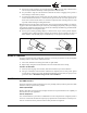
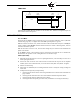
8. Proven types of flame grounding adapters, as shown below, may be used to provide adequate
grounding surface. High temperature stainless steel should be used to minimize the effect of
metal oxidation. This assembly may be welded directly over the pilot or main burner nozzle.
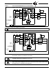
WIRING OF FLAME RODS
For proper operation of flame rectification systems, it is necessary to maintain at least 20 megohms
insulating resistance in the flame rectification circuit.
1. The scanner should be wired using metal cable or rigid conduit.
2. High voltage wiring must not be installed in the same conduit with scanner wiring.
Selection of Scanner Wire
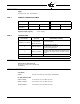
1. Use #14, 16, or 18 gauge wire with 90 C, 600 volt insulation for up to 20 feet distance.
2. The type of insulation used with flame rectification is important, since it must protect against
current leakage resistance to ground. Use Belden 8254-RG62 Coaxial Cable (or equal) for runs
greater than 20 feet. Maximum wiring run not to exceed 100 feet.
MAINTENANCE
Type 69ND1 Flame Rod
The flame rod and its insulator should be kept clean by washing routinely with soap and water. Rods
should be routinely replaced as they oxidize.
Flame Signal Strength
Routine observation of the flame signal strength will forewarn any deterioration in the capability of
the flame detector or its application.
Periodic Safety Check
It is recommended that a procedure be established to test the complete flame safeguard system at
least once a month. This test should verify the proper operation of all limit switches and safety inter-
locks as well as flame failure protection and fuel safety shutoff valve tightness.
BOMB FIN
GROUNDING
ASSEMBLY
THREADED ROD
ASSEMBLY