
Product Overview


6
®
Pilot Trial for Ignition
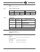
Jumpers JP6 and JP7 are used by the factory only to select the PTFI for the M4RT1. The available
PTFI timing selections are 5 and 10 seconds. The factory set, default PTFI time is 10 seconds (JP6
installed, JP7 not installed). The PTFI time may only be set by the factory.
Recycle/Non-recycle Operation
Jumper JP8 is used to select either Recycle or Non-Recycle operation of the M4RT1. The factory
set, default is Recycle operation (JP8 installed). To select Non-Recycle operation, cut jumper JP8.
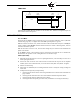
LED INDICATOR LIGHTS
The M4RT1 has 5 LED lights to indicate the operating status of the control. The function of these
lights are:
Opr Ctrl (Operating Control): This LED is lighted whenever input terminal 7 is energized. The
burner system safety interlocks and operating control should be wired in series and connected to the
M4RT1 terminal 7.
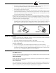
Air Flow: This LED is lighted whenever all of these conditions exist:
— Input terminal 7 is energized (operating control and safety interlocks closed).
— Input terminal 6 is energized (proof of airflow switch is closed).
— Output terminal 8 is energized (blower motor).
PTFI: This LED is energized only during the Pilot Trial For Ignition Period.
Flame: This LED is lighted whenever an adequate flame signal is detected between the M4RT1
terminals S1 & S2.
Alarm: This LED is energized whenever a safety lockout occurs. (See APPLICATION AND
FUNCTION section).
NOTE: The M4RT1 is not powered until the user’s operating control is energized.
APPLICATION AND FUNCTION
The M4RT1 provides prepurge, ignition and flame safeguard for heating and process gas fired burn-
ers. The “recycle” or “non-recycle” operation is determined by the #8 jumper on the top PCB. Purge
timing, as well as trial for ignition timing is also set by the jumpers. See JUMPER SETTINGS on
page 5.
The M4RT1 amplifier circuitry is designed to utilize a flame rod for flame detection. The Flame Fail-
ure Response Time (F.F.R.T.) is fixed at 3 seconds.
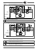
Pilot Ignited Burners - “Recycle” Operation
With jumper #8 in the “recycle” position, the typical wiring arrangement illustrated on page 10 for
pilot ignited burners provides the following function:
1. With power applied to Terminal 7 (Opr Ctrl LED lighted), the burner motor circuit (Terminal 8)
is energized. The control then waits for the proof of airflow input (Terminal 6) to be energized
2. The Pre-Purge timing starts when terminal 6 is energized.
3. Following the prepurge period (as determined by jumpers #1 through #5), KL-1 closes, ener-
gizing Terminal 3 which powers the pilot gas valve and Terminal 4 which powers the spark igni-
tion. A five or ten sec. (as determined by jumpers #6 or #7) trial for ignition is initiated (
PTFI
LED lit).
4. When pilot flame is detected (Flame LED lit), KF-1 closes, energizing Terminal 5 which powers
the main fuel valve, KF-2 opens de-energizing Terminal 4 which shuts off the spark ignition.
5. When the operating control opens its circuit, or if a power failure occurs, the entire system is de-
energized. Power interruptions in the millisecond range do not affect the operation of the con-
trol. Power interruptions of longer duration will cause the control to recycle.