
Product Overview


8
®
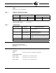
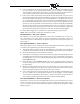
TIMING CHART
Selectable Recycle/Non-Recycle operation on loss of flame after Terminal 5 energized. Recycle on
loss of air flow after flame proven.
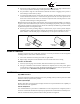
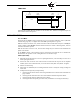
INSTALLATION TESTING
Use of Test Meter
Testing the Fireye M4RT1 Control requires the use of a test AC-DC multimeter, with a 1,000 ohm/
volt DC rating or greater, or a digital meter with 500K input impedance or greater.
With the test meter on the DC scale, and the test meter leads inserted into the test jacks. A steady DC
voltage reading of 6 to 18 volts should be obtained when the control is detecting flame, and zero
volts when no flame is present.
With the test meter on the AC scale, line and load voltages may be measured at the identified test
points on the chassis.
On the M4RT1 control, a micro-ammeter may be connected in series with the wire to Terminal S2.
Normal flame will produce a meter reading between 4 and 10 micro-amps.
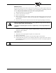
Flame Signal Testing
1. Manually shut off the main fuel valve for a pilot ignited burner, or the secondary fuel valve for a
direct spark ignited burner.
2. Set the test meter on the DC scale and insert the test leads into the test jacks on the amplifier
module. (If the meter reads backwards, reverse the meter leads). Red - Plus, Black - Negative.
3. Initiate a normal startup.
4. When flame is established, the test reading should be normal: a steady DC voltage reading of 6
to 18 volts.
5. Inadequate flame signal may be improved by:
a Assuring that the flame detector and wiring installations have followed the instructions on
pages 3 and 4.
b Assuring that the flame detector is clean and within the ambient temperature limits.
c Assuring that the flame is sufficiently large to detect.
d Assuring that the flame quality (fuel to air ratio, combustion air velocity) is satisfactory.
PROGRAMMING SEQUENCE
7
ON
PURGE
COMPLETE
FIRING
PERIOD
7
OFF
SELECTABLE PTFI
5 OR10 SEC
SELECTABLE
PURGE
8
T
E
R
M
I
N
A
L
S
3
4
5
AIR
FLOW
PROVEN