A p e xT M Action PrinterTM T-1000 by EPSON User’s Manual Y56599116000
Where to Get Help Customer support and service for Epson products are provided by a network of authorized Epson dealers and service centers throughout the United States. Epson America provides product information and toll-free support to its dealers and service centers. Epson is confident that this policy will provide you with the assistance you need. For service center and technical support referrals, please call our Consumer Information number: l-800-922-891 1.
A p e xT Action Printer M TM User‘s Manual T-1000 by EPSON ®
Contents 1 Introduction Features . . . . . . . . . . . . . . . . . . . . . . . . . . . . . . . . . . . . . . . . . . About This Manual . . . . . . . . . . . . . . . . . . . . . . . . . . . . . . . . . 1 2 Chapter 1 Setting Up l-1 Identifying Printer Parts . . . . . . . . . . . . . . . . . . . . . . . . . . . . . Selecting a Place for the Printer . . . . . . . . . . . . . . . . . . . . . . . Installing the Paper Feed Knob . . . . . . . . . . . . . . . . . . . . . . . .
Chapter 5 Defaults and DIP Switches 5-1 Default and Initialization Settings . . . . . . . . . . . . . . . . . . . . . DIP Switch Settings . . . . . . . . . . . . . . . . . . . . . . . . . . . . . . . . . International Character Sets . . . . . . . . . . . . . . . . . . . . . . . . . . 5-2 5-3 5-5 Chapter 6 Technical Specifications 6-1 6-2 6-2 6-3 6-3 6-4 6-5 6-7 Printing.. . . . . . . . . . . . . . . . . . . . . . . . . . . . . . . . . . . . . . . . . . Paper . . . . . . . . . . . . . . . . . . . . . .
Introduction The ActionPrinterTM T-1000 combines low price with high quality printing and advanced features. Features In addition to the high performance and reliability you’ve come to expect from Epson® printers, this printer offers the following features: Draft mode for quick printing. The speed of draft printing is 150 characters per second in pica and 180 in elite. Near Letter Quality (NLQ) mode for top quality printing.
Introduction About This Manual Chapter 1 gives you step-by-step instructions on setting up your new printer, and Chapters 2 through 6 cover the basic and advanced functions. Chapter 7 contains a summary of the printer’s commands, and the Appendix contains information on optional interfaces. Attached to the cover of this manual is a Quick Reference card containing the information you need most.
Chapter 1 Setting Up Identifying Printer Parts . . . . . . . . . . . . . . . . . . . . . . . . . . . . . . 1-2 Selecting a Place for the Printer . . . . . . . . . . . . . . . . . . . . . . . . 1-4 Installing the Paper Feed Knob . . . . . . . . . . . . . . . . . . . . . . . . 1-5 Installing and Replacing the Ribbon . . . . . . . . . . . . . . . . . . . . Replacing the ribbon . . . . . . . . . . . . . . . . . . . . . . . . . . . . . . 1-6 1-8 Using Continuous-feed Paper . . . . . . . . . . . . . . .
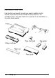
Identifying Printer Parts First, see that you have all the parts you need. In addition to this manual, the printer box should contain the items shown in the illustration below. The paper feed knob is packed into an indentation in the white foam material.
Identifying Printer Parts In addition to the items in the box, you need a proper shielded cable to connect the printer to your computer. Though unlikely, you may also need an interface board, which is necessary only for those computers that can’t use the Centronics® parallel interface. Your computer manual can tell you which cable you need and whether or not you require a special interface.
Selecting a Place for the Printer The main consideration in selecting a good location for the printer is placing the printer close enough to your computer for the cable to reach. Also remember the following: Plug the printer into a grounded outlet, and do not use an adapter plug. Make sure the power switch on the printer’s left side is off before plugging in the printer. Avoid using electrical outlets that are controlled by wall switches.
Installing the Paper Feed Knob Now that you have decided where to locate your printer, the first step in setting it up is installing the paper feed knob. Follow these steps: 1. Locate the paper feed knob, which is packed into an indentation in the white foam material. 2. Insert the knob into the hole on the right side of the printer, as shown below. Gently rotate the knob until it fits over the shaft. 3. Push the knob in until it is flush with the printer case.
Installing and Replacing the Ribbon The printer uses a continuous-loop, inked fabric ribbon. It is enclosed in a cartridge that makes ribbon installation and replacement a clean and easy job. To install the ribbon, follow these steps: 1. Remove the lid at the front of the printer by lifting the handles. Removing the lid enables you to see the print head, which is shown below.
installing and Replacing the Ribbon 2. Move the print head by hand to the center of the printer so that the other parts of the printer will not get in your way. 3. Grasp the ribbon cartridge by its handle and hold the cartridge so that the exposed strip of ribbon is facing away from you. 4. Insert the cartridge by placing the black hooks on each side of the cartridge into the slots located inside the printer in the right and left front corners. Push down until the cartridge snaps into place.
installing and Replacing the Ribbon 5. Turn the knob on the cartridge in the direction of the arrow to tighten the ribbon. As you turn the knob, see that the ribbon slips down into its proper place between the print head and the ribbon guide. You may want to use a pen to direct the ribbon, as shown in the next illustration. 6. Replace the front lid by inserting its legs into the slots near the front comers of the printer. Lay the lid down and press to snap it into place.
Using Continuous-feed Paper The following section covers use of continuous-feed paper with your tractor unit. If you plan to use single-sheet paper, skip to the “Removing the tractor unit” section on page 1-17. The tractor unit for the printer allows you to use paper with pin feed holes along the sides (continuous-feed paper). You can adjust the tractor unit to accommodate widths of paper ranging from 4 to 10 inches, including the pin feed holes.
Using Continuous-feed Paper 2. Pop out the tractor unit slot cover, which is located above the indicator lights. It may help to use the flat edge of a screwdriver, as shown on the next page. Store the cover in a safe place while you use the tractor unit, and replace it when you remove the tractor unit. 3. 1-10 Fit the paper rest into the slots along the top edge of the back of the printer and snap it into place, as shown below.
Using Continuous-feed Paper 4. Pull the paper release lever forward. (See the illustration below.) The double-arrow icon in front of the lever marks the position the lever should be in for using continuous-feed paper (or for releasing paper). 5. Now install the tractor unit. First, hold the unit so that its black legs are facing downward, as shown below.
Using Continuous-feed Paper 6. In each tractor slot, located at each side of the paper slot, is a peg that fits into the notch on each of the rear tractor legs. Tilt the tractor back so that the rear notches fit over these pegs, as shown below. 7. Then tilt the unit forward until the front legs snap into place. Loading continuous-feed paper Once the tractor unit is installed, load continuous-feed paper as follows: 1. Make sure that the printer is turned off. 2. Remove the front lid of the printer. 3.
Using Continuous-feed Paper 4. Using the illustration below as a guide, pull the locking levers on each side of the pin feed holders forward so you can move the pin feed holders. 5. Place the left holder approximately 3/4 of an inch from the far left position and then push the locking lever back to fasten that holder into place. Leave the other holder unlocked. 6. Open the pin feed covers as shown below. 7. Feed the paper into the paper slot.
Using Continuous-feed Paper 8. Pull the paper up until the top is above the pin feed holders. Fit the holes along the left edge of the paper over the pins in the left holder, as shown below, and close the pin feed cover. 9. Fit the right side of the paper into the right holder, moving the holder as needed to match the width of the paper. Close the second pin feed cover. 10. Make sure that the paper has no dips or wrinkles, then push the locking lever back to lock the right holder in place.
Using Continuous-feed Paper For continuous-feed paper, move the edge guides to the far right and left positions on the paper guide. You won’t be inserting paper through the edge guides unless you use single-sheet paper. 2. Insert the legs of the paper guide into the slots behind the tractor unit, keeping the guide tilted backward as you do so. (See the illustration below .
Using Continuous-feed Paper 3. When the legs are in the slots, lean the guide all the way back. The guide should rest above the paper entering the printer, separating it from paper exiting the printer. Setting top of form Now you are ready to set the top of form position. Follow these steps: 1. Turn the paper feed knob to advance the paper until the perforation between pages is just below the top of the ribbon. 2. Now replace the front lid. Your printer should now be set up as shown below.
Using Continuous-feed Paper Once you have set the top of form, each time you finish printing a document, push the ON/OFF LINE button to put the printer off-line and then push the FORM FEED button once to advance the paper one sheet. This enables you to tear off your just-printed pages and leave the paper in the correct position to begin the next document. Note: Make sure that the front lid is in place whenever you print. (Always snap the lid shut when replacing the lid.
Using Single-sheet Paper Before you load single-sheet paper, you must prepare the printer by installing the paper guide in an upright position. If the tractor unit is installed, remove it by following the instructions above. After following those instructions, you can skip the following section on paper guide installation, except for step 3 on aligning the left edge guide. Installing the paper guide Install the paper guide as follows: 1.
Using Single-sheet Paper 3. Align the left side of the left edge guide with the guide mark on the paper guide as shown below. You may later wish to adjust this edge guide depending on the margin setting in your application program. Guide Automatic paper loading Now you are ready to load single-sheet paper using the printer’s auto load feature. To load paper automatically, just follow these steps: 1. Push back the paper release lever. (See the illustration on the previous page.
Using Single-sheet Paper 6. Press and release DRAFT/LINE FEED top of the page. the AUTO LOAD button (the same button as the button). The paper is automatically loaded to the 7. Push the ON/OFF LINE button so that the printer is ready to print. Note: Make sure the front lid is in place whenever you print. (Always snap the lid shut when replacing the lid.) The front lid doubles as a paper bail, holding the paper against the platen. 8.
Using Single-sheet Paper Reloading during printing When you print a document more than one page long using single-sheet paper, there are two ways your software can enable you to load a new sheet at the end of a page: l l If your software sends characters in a continuous stream, the printer stops printing when it reaches the bottom of the paper. When this happens, the ON LINE light goes off automatically.
Operating the Control Panel Now that your paper is loaded, it is time to see what the indicators and buttons on the control panel do. First, see that the power switch on the left side of the printer is on. Then take a look at the control panel. (See the following illustration.) - POWER - READY - PAPER OUT There are four indicator lights and three buttons on the control panel.
Operating l l the Control Panel The PAPER OUT light glows red to indicate that the printer is out of paper or the paper is loaded incorrectly. If you try to print and the printer does not respond, check to see if this light is on. The ON LINE light glows green when the printer can receive data. (The ON LINE light is located on the ON/OFF LINE button.) Buttons The buttons, or touch-sensitive panels, have several functions, including selecting draft or NLQ (Near Letter Quality) printing.
Operating the Control Panel . DRAFT/LINE FEED. When the printer is off line, pressing this button advances the paper one line. When the printer is on line, pressing this button selects draft printing. When you select draft printing the beeper sounds once. This button also controls the auto load feature. The control panel buttons also control the SelecType feature. This feature enables you to select among emphasized, double-strike, condensed, and elite typestyles. See Chapter 2 for more information.
Operating the Control Panel DRAFT ’ ( ) * + , - . / 0123456789: ;<=>?@ ABCDEFGHIJLMNO ( ) *+,-./0123456789: ; <=>?@ABCDEFGHIJKLMNOP ) * + , - . /0123456789 : ; <=>?@ A B C D E F G H I J K L M N O P Q *+,-./ 0 2 3 5 6 7 8 9 : ; < = > ? @ ABCDEFGHIJKLMNOPQR + , - . /0123456789: ; <=>?@ A B C D E F G H I J K L M N O P Q R S ,-- . /0123456789 : ; <=>?@ A B C D E F G J H I J K L M N O P Q R S T ,-.
Connecting the Printer to Your Computer Now that the test pattern has shown that your printer is operational, it’s time to hook it up to your computer. Remember that computer systems communicate with printers in a variety of ways. If your computer expects to communicate through a Centronics parallel interface, all you need is the proper shielded cable. If your computer requires any other kind of interface, you also need an interface board.
Connecting the Printer to Your Computer 3. Secure the plug to the printer with the wire clips on each side of the connector. Press the clips into the metal clasps at each side of the plug. These clips ensure that your cable will not be loosened or unplugged accidentally. 4. If your cable has a grounding wire, fasten it to the grounding screw below the connector. 5. Connect the other end of the printer cable to your computer.
Printer Selection Menus Most application programs let you specify the type of printer you’re using so that the program can take full advantage of the printer’s features. Many programs provide an installation or setup procedure that presents a list of printers to choose from. Choosing from a menu Because the family of Epson printers shares a great many commands, you can use an application program even if it does not list your printer on its printer selection menu.
Chapter 2 SelecType SelecType Operation . . . . . . . . . . . . . . . . . . . . . . . . . . . . . . . . Turning SelecType on . . . . . . . . . . . . . . . . . . . . . . . . . . . . . . Selecting typestyles . . . . . . . . . . . . . . . . . . . . . . . . . . . . . . . . SelecType Tips . . . . . . . . . . . . . . . . . . . . . . . . . . . . . . . . . . . . .
SelecType Operation The printer’s SelecType feature can produce four special typestyles: This is emphasized printing. This is in the double-strike mode. This is condensed printing. ‘This is in the elite mode. Using SelecType is easy. You turn on SelecType and select a typestyle, then turn off SelecType and print. Turning SelecType on 1. Make sure that the printer is on line. 2. 2-2 Hold down the ON/OFF LINE button and press the FORM FEED button. (See the illustration below.
SelecType Operation Selecting typestyles In SelecType, each button has a function: l ON/OFF LINE l FORM FEED l LINE FEED selects typestyles. sets the styles. turns SelecType off. After turning on SelecType, follow these steps to select a typestyle: 1. Find the typestyle you want in the table below. All of the typestyles listed in the table are available for draft mode. If you are in NLQ mode, only emphasized and elite are available.
SelecType Operation When you press the ON/OFF LINE button to select an additional mode, start counting again where you left off. That is, if you have selected emphasized and wish to combine that with elite, press the ON/OFF LINE button three more times, not four, to select elite. For example, follow these steps to combine emphasized and elite: 1. Press the ON/OFF LINE button once to select emphasized. 2. Press the FORM FEED button. 3. Press the ON/OFF LINE button three more times to select elite.
SelecType Tips Once you have learned the simple technique for controlling print styles with SelecType, you can use it whenever you wish. You should be aware of a few points, however. SelecType is designed to control the printing of an entire file or document, not an individual line or word. If you are using the NLQ mode, remember that the following SelecType modes are not available: double-strike and condensed.
SelecType Tips 2-6 SelecType
Chapter 3 Printer Features Quality and Fonts . . . . . . . . . . . . . . . . . . . . . . . . . . . . . . . . . . . 3-2 Print Size and Character Width . . . . . . . . . . . . . . . . . . . . . . . Pitches . . . . . . . . . . . . . . . . . . . . . . . . . . . . . . . . . . . . . . . . . . Double-wide and condensed . . . . . . . . . . . . . . . . . . . . . . . . 3-3 3-3 3-3 Special Effects and Emphasis . . . . . . . . . . . . . . . . . . . . . . . . . . 3-5 Using Different Character Sets . . . . . . . .
Quality and Fonts The most fundamental changes you can make to printing are in the print quality and NLQ fonts. The printer has two levels of print quality: draft and NLQ (Near Letter Quality). Draft printing is fast, making it ideal for drafts and other preliminary work. NLQ printing takes a little longer, but it produces more fully-formed characters for presentation-quality documents.
Print Size and Character Width To add greater variety to your documents, the printer has two pitches and condensed printing. All can be selected either with SelecType or a software command, and software commands also offer another option: double-wide. Pitches The two pitches are pica and elite. Pica is 10 characters per inch (cpi) and elite is 12 cpi. The printout below shows the difference between the two.
Print Size and Character Width Condensed can be selected with SelecType, by setting a DIP switch (see Chapter 5), or with a software command. Even if you turn condensed on with the DIP switch, you can still turn it off with SelecType or the software command. Condensed pica gives more characters on a line. Condensed elite gives you even mare. Widening or narrowing the characters also widens or narrows the spaces between words and letters.
Special Effects and Emphasis The printer offers two ways of emphasizing parts of your text and also allows you to use underlining, superscripts, and subscripts. Most of these features can be controlled only by software commands, but many application programs can produce them if they are properly installed. Emphasized and double-strike modes, both of which can be chosen with SelecType, slow the printer down slightly to produce bolder text.
Using Different Character Sets The printer incorporates a special character set: Epson Character Graphics. This set allows you to take, advantage of the power of the Epson commands and still print out the character graphics used by IBM and IBM-compatible computers and by much commercial software. For example, if your word processor can include the characters to draw boxes and shade areas, you can produce some very professional effects.
Using Different Character Sets 35 36 64 91 92 93 94 96 123 124 125 126 0 USA 1 France 2 Germany 3 UK 4 Denmark I 5 Sweden 6 Italy 7 Spain I 8 Japan 9 Norway 10 Denmark II 11 Spain II 13 Latin America Also, all text characters can be printed in italics. You can use this typestyle for special emphasis or as an alternative typeface. Italics give emphasis to words. They are an attractive alternative style.
Using Different Character Sets 3-8 Printer Features
Chapter 4 Troubleshooting and Maintenance Problem/Solution Summary . . . . . . . . . . . . . . . . . . . . . . . . . . 4-2 Beeper Error Warnings . . . . . . . . . . . . . . . . . . . . . . . . . . . . . . . 4-4 Cleaning the Printer . . . . . . . . . . . . . . . . . . . . . . . . . . . . . . . . . 4-5 Transporting the Printer . . . . . . . . . . . . . . . . . . . . . . . . . . . . . .
Problem/Solution Summary Problem Solution Printer does not print Make sure that the printer is turned on and is on line. Both the POWER and ON LINE lights should be on. Make sure that the printer and computer are connected. Be certain you are using the correct cable and that it is firmly plugged in at both ends. Turn the printer off and on again to reset it. While the printer is turned off, make sure the paper is loaded correctly.
Problem/Solution Summary Problem Solution All the text is printed on the same fine or text is printed with an extra blank line This can usually be corrected by changing the setting of DIP switch 2-4. If that does not solve the problem, you may need a different cable. Some of the characters printed do not match those in the If they are international characters, check the settings of DIP switches 1-6 to l-8.
Beeper Error Warnings When the printer’s beeper sounds, it usually indicates that the printer is out of paper. If the printer beeps and stops printing when it is not out of paper, turn the printer off and check to see that the paper is loaded correctly. If the paper is loaded correctly, turn the printer back on and try to print again. If the printer beeps and does not print again, take it to a qualified service person.
Cleaning the Printer To keep your printer running at its best, you should clean it thoroughly several times a year. Follow the steps below: 1. Make sure the printer is turned off. Then remove the paper guide. 2. Using a soft brush, carefully remove all dust and dirt. 3. If the outer case or paper guide is dirty or dusty, clean it with a soft, clean cloth dampened with a mild detergent solution. Keep the front lid in place to prevent water from getting inside the printer.
Transporting the Printer Before you transport your printer some distance, carefully repack it in the original box and packing materials as described in the following instructions: 1. Make sure the printer is turned off. Then remove the paper guide and front lid. WARNING: Turn the printer off before unplugging the power cable from the AC outlet. 2. Unplug the power cable from the electrical outlet. Coil the cable and tie it. Then disconnect the interface cable from the printer and computer. 3.
Chapter 5 Defaults and DIP Switches Default and Initialization Settings . . . . . . . . . . . . . . . . . . . . . . 5-2 DIP Switch Settings . . . . . . . . . . . . . . . . . . . . . . . . . . . . . . . . . 5-3 International Character Sets . . . . . . . . . . . . . . . . . . . . . . . . . .
Default and Initialization Settings The printer can be initialized (returned to a fixed set of conditions) in three different ways: when it is turned on, when it receives an INIT signal at the parallel interface (pin 31 becomes low), and when it receives the ESC @ command. The following conditions always occur when the printer is initialized: The print head returns to the home position. Interface signals are reset, and the printer is put on line. The current print line is cleared.
DIP Switch Settings The printer has twelve DIP switches which allow you to change many of the printer’s settings to suit your individual needs. The DIP switches are in two groups, mounted on the back panel, as shown below. DIP switch l-1 is the switch at the far left side, and the one at the far right is DIP switch 2-4. You can easily reset the switches with a thin, pointed object such as a small screwdriver or the cap of a ballpoint pen.
DIP Switch Settings The tables below describe the DIP switch functions. DIP Switch 1 Switch number 1-1 1-2 1-3 1-4 1-5 1-6 1-7 1-8 Function Select condensed or normal characters Select slashed or unslashed zero Select character table Paper-out detection Select print quality Select international character set Action when ON Condensed 0 Graphics Inactive NLQ See table on page 5-5 DIP Switch 2 Add line feed after carnage return Note: The factory setting for all switches except l-6. l-7.
International Character Sets Thirteen international character sets are available. Eight of these are selected by DIP switches 1-6 to 1-8, and the remaining five (Japan, Norway, Denmark II, Spain II and Latin America) can be selected with the ESC R command, which is described in the Command Summary (Chapter 7). For the characters available in each character set, see Chapter 3. The DIP switch settings to select the different character sets are shown below.
Chapter 6 Technical Specifications Printing . . . . . . . . . . . . . . . . . . . . . . . . . . . . . . . . . . . . . . . . . . . 6-2 Paper . . . . . . . . . . . . . . . . . . . . . . . . . . . . . . . . . . . . . . . . . . . . . 6-2 Mechanical . . . . . . . . . . . . . . . . . . . . . . . . . . . . . . . . . . . . . . . . 6-3 Electrical . . . . . . . . . . . . . . . . . . . . . . . . . . . . . . . . . . . . . . . . . . 6-3 Environment . . . . . . . . . . . . . . . . . . . . . . . . . . . . . . . . . .
Technical Specifications Printing Printing method: Impact dot matrix Printing speed: 180 characters per second in draft elite. 150 characters per second in draft pica. 25 characters per second in NLQ pica Printing direction: Bidirectional logic-seeking for text printing. Unidirectional for graphics and by software command for text Character sizes: All except superscript and subscript are 3.1 mm high.
Technical Specifications Mechanical Ribbon: Cartridge, black #8750 Life expectancy (in characters, at 14 dots/character): 3 million MCBF: 3 million lines (excluding the print head) MTBF: 4,000 hours Print head life: 200 million strokes per wire Dimensions and Weight: 3.5 in. Height (excluding tractor): Width (with paper feed knob): 15.7 in. 12.1 in. Depth: Weight (including tractor): 11.2 lbs.
Technical Specifications Environment Temperature: Operation: 41° F to 95º F (5 C° to 35 C°) Storage: -22” F to 149° F (-30 Cº to 60 Co) Humidity: Operation: 10% to 80% without condensation Storage: 5% to 85% without condensation Shock: Operation: Up to 1 G within 1 ms Storage: Up to 2 G within 1 ms Vibration: Operation: Up to 0.25 G at up to 55 Hz Storage: Up to 0.
Technical Specifications Parallel Interface Connector pin assignments and a description of respective interface signals are shown below and on the following page. Signal Return Pin Pin Signal Direction Description 1 19 STROBE IN STROBE pulse to read data in. Pulse width must be more than 0.5 µs at the receiving terminal.
Technical Specifications Signal Pin Return Pin Direction Signal 16 - OV 17 - CHASSIS Description - Logic ground level. GND - from the logic ground. Unused. Printer's chassis ground, which is isolated - NC - 19-30 - GND - Twisted-pair return signal ground level. 31 - INIT I N When level becomes LOW, the printer 18 controller is reset to its power-up state and the print butter is cleared.
Technical Specifications The column heading “Direction” refers to the direction of signal flow as viewed from the printer. “Return” denotes the twisted-pair return, to be connected at signal ground level. For the interface wiring, be sure to use a twisted-pair cable for each signal and to complete the connection on the return side. To prevent noise, these cables should be shielded and connected to the chassis of the host computer or the printer but not at both ends.
Technical Specifications Printing enabled/disabled signals and control conditions The table below shows the relationship between printing being enabled or disabled, and the on line/off line condition, the printer select signal (SLCT IN), and the receipt of data on/off control character, DC1/DC3. ON LINE (Indicator) DC1/DC3 ERROR BUSY (Data on/off control) Low (Sw. DC1/DC3 High (no effect) High/Low Pulsed ea. Enabled (normal char. cond.
Chapter 7 Command Summary Introduction . . . . . . . . . . . . . . . . . . . . . . . . . . . . . . . . . . . . . . . 7-2 Printer Operation . . . . . . . . . . . . . . . . . . . . . . . . . . . . . . . . . . . 7-2 Data Control . . . . . . . . . . . . . . . . . . . . . . . . . . . . . . . . . . . . . . . 7-2 Vertical Motion . . . . . . . . . . . . . . . . . . . . . . . . . . . . . . . . . . . . . 7-3 Horizontal Motion . . . . . . . . . . . . . . . . . . . . . . . . . . . . . . . . . .
Command Summary Introduction This summary contains all the commands used by the printer. If a command has no parameters, it is merely listed. If it has parameters, they are explained. The parameters are indicated by lowercase italicized letters, usually n. The examples below show how the parameters are indicated. ESC @ is a command with no parameters. ESC U 1/0 is a command that uses 1 to turn the feature on and 0 to turn it off. ESC $ nl n2 is a command with two parameters.
Command Summary ASCII Dec. Hex. Description Vertical Motion FF ESC C n 12 0C 67 43 ESCCOn 67 43 ESC N n 78 4 E ESC0 LF ESC 0 ESC 1 ESC 2 ESC3n ESCAn ESCJn VT ESC B nn 79 4F 10 0A 48 30 49 31 50 32 51 33 65 41 74 4A 11 0B 66 42 ESC b nn 98 62 ESC / n 47 2F Form Feed Set Page Length in Lines n = no. of lines (1-127) Set Page Length in Inches n = no. of inches (l-22) Set Skip Over Perforation n = no.
Command Summary Dec. Hex.
Command Summary ASCII Dec. Hex.
Command Summary ASCII Dec. Hex.
Appendix Compatible Interfaces . . . . . . . . . . . . . . . . . . . . . . . . . . . . . . . A-2 Installing an Interface . . . . . . . . . . . . . . . . . . . . . . . . . . . . . . . Inserting the interface board . . . . . . . . . . . . . . . . . . . . . . . . A-3 A-6 #8143 New Serial Interface Board . . . . . . . . . . . . . . . . . . . . . Error handling . . . . . . . . . . . . . . . . . . . . . . . . . . . . . . . . . . .
Compatible Interfaces There are two optional interfaces that supplement the built-in parallel interface.
Installing an Interface Before installing an interface, you must remove the printer’s cover. WARNING: Do not remove the cover unless the printer is turned OFF and unplugged because high voltages are present inside the printer when the power is on. Also, do not touch contacts on the circuit board of the printer because many of the components can be destroyed by the static electricity charge that may build up on your body. 1.
Installing an lnterface 5. Slightly raise the upper case by its front. As you do this, be careful not to pull the flat cable out of the control panel in the upper case.
Installing an Interface 6. Disconnect the other end of the flat control panel cable from the main circuit board connector as shown in the illustration. After you remove the case, follow the instructions below to insert the interface board. After you have inserted the board, replace the case by reversing steps 2 through 6.
installing an Interface Inserting the interface board 1. Locate the connector cover at the back of the upper case, shown in the illustration below. Push it down and in, toward the inside of the printer, until it clicks. You need to move the cover to allow access to the new interface connector when the case is reassembled. 2. The screw marked CG at the rear of the circuit board is the connection for the frame ground wire. Unscrew it and then use it to connect the frame ground wire as shown below.
Installing an lnterface 3. Plug the interface board into the connector marked CN2 on the main circuit board of the printer. 4. Secure the board to the three supports with the screws provided, as shown below.
Installing an Interface 5. Connect the frame ground wire to the FG terminal tag on the interface board, as shown below. 6. Reassemble the printer, reversing the procedure described in steps 2 through 6 in the previous section.
#8143 New Serial Interface Board If you are using an optional interface, it may be necessary for you to alter the communications protocol of the printer or the computer so they can communicate properly. In most cases, you should use the information in your optional interface manual or your computer’s manual to match the computer with the interface. For the #8143 optional interface board, use the DIP switch settings shown below. These switches are on the interface board, not on the printer.
#8143 New Serial lnterface Board #8143 baud rate selection Baud rate SW1-7 SW1-1 SW1-4 SW1-3 75 ON ON ON ON 110 ON O N ON OFF 134.
Index Command descriptions are not indexed here. To locate a specific command, see Chapter 7 or the Quick Reference card.
I Indicator lights, l-22 - 23 Initialization, 5-2 Interface boards, A-2 - 10 compatibility, A-2 installation, A-2 - 8 new serial interface #8143, A-9 - 10 International character sets, 3-6, 5-5 Italic mode, 3-7, 7-6 L LlNE FEED button, l-25 M Multi-part forms, 1-21 N Near letter quality (NLQ), l-23, 3-2, 7-4 NLQ/FORM FEED , button, l-23 0 ON LINE light, l-23 ON/OFF LINE button, l-23 P Paper, copy capacity, 6-2 loading, 1-9 - 21 multi-part forms, 1-21 top of form, l-16-17 width, 6-2 Paper feed knob, l-5
S w Sans serif font, l-23, 3-2, 7-4 SelecType, 2-l - 5 Self-test, printer, l-24 - 25 Single-sheet paper, l-18 - 21 loading, 1-19 - 21 Software, application, l-28 controlling printer features, 7-l-8 Special printing effects, 3-5 Specifications, 6-l - 8 parallel interface, 6-5 - 8 printer, 6-2 - 4 Subscript mode, 3-5 Superscript mode, 3-5 Word processing, 7-6 T Technical specifications, see Specifications Top of form, l-16-17 Tractor unit, installing, l-9 -12 removing, 1-17 Tractor unit slot cover, l-9-10
4 Index
Quick Reference Edge guides Paper fed knob Control panel Print head Ribbon cartridge Power switch I Parallel interface DIP‘ switches
Commands Arranged by Topic ASCII Dec. Hex.
ASCII Dec. Hex.
Dec. Hex.
FCC COMPLIANCE STATEMENT FOR AMERICAN USERS This equipment generates and uses radio frequency energy and if not installed and used properly, that is, in strict accordance with the manufacturer’s instructions, may cause interference to radio and television reception.
Epson America, Inc. 2780 Lomita Boulevard Torrance, CA 90505 Printed in Japan 89.02-9.