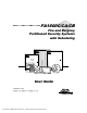
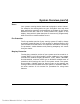
)$ & &$ &% )LUH DQG %XUJODU\ 3DUWLWLRQHG 6HFXULW\ 6\VWHPV ZLWK 6FKHGXOLQJ **** **** A ARMED OFF AWAY FIRE FIRE STAY 1 2 3 MAXIMUM TEST BYPASS 4 5 6 INSTANT CODE CHIME 8 9 0 # 7 First Alert B D C READY PULL READY * Professional 8VHU *XLGH N6020-4V2 1/99 Technical Manuals Online! - http://www.tech-man.
TABLE OF CONTENTS SYSTEM OVERVIEW .................................... 4 General....................................................... 4 A Partitioned System .................................. 4 Zones.......................................................... 5 Fire Protection ............................................ 5 Burglary Protection ..................................... 5 Alarms ........................................................ 6 Memory of Alarm ........................................
SPEED KEY (MACROS) ..............................41 General Information ..................................41 Defining.....................................................41 Executing ..................................................42 ACCESS DOOR CONTROL ........................43 General Information ..................................43 Executing ..................................................43 USING #70 RELAY MENU MODE ...............44 General Information ..................................
System Overview General Congratulations on your ownership of an First Alert Partitioned Security System. You've made a wise decision in choosing it, for it represents the latest in security protection technology today. Ademco is the world's largest manufacturer of security systems and millions of premises are protected by First Alert systems. This system offers you three forms of protection: burglary, fire and emergency.
System Overview (cont’d) Zones Your system's sensing devices have been assigned to various "zones." For example, the sensing device on your Entry/Exit door may have been assigned to zone 001, sensing devices on windows in the master bedroom to zone 002, and so on. These numbers will appear on the display, along with an alpha descriptor for that zone (if programmed), when an alarm or trouble condition occurs.
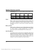
System Overview (cont’d) The following table lists the four different arming modes and the results of each. Arming Mode AWAY STAY INSTANT MAXIMUM Exit Delay Yes Yes Yes Yes Features For Each Arming Mode Entry Perimeter Interior Delay Armed Armed Yes Yes Yes Yes Yes No No Yes No No Yes Yes Alarms When an alarm occurs, both the keypad and external sounders will sound, and the keypad will display the zone(s) causing the alarm.
System Overview (cont’d) Using Schedules Your system may have been programmed with schedules for automatically arming, disarming and activating various devices and/or performing other system functions at predetermined times. Users can modify some of these schedules by manually delaying a closing time, using temporary schedules, or by programming special user schedules. Refer to the USING SCHEDULES section at the end of this manual for scheduling related procedures.
System Overview (cont’d) Master Keypad Operation A "Master" keypad is one on which the status of all 8 partitions is displayed simultaneously. A user can get more information about a certain partition by simply entering ✴ + the desired partition number (1-8). To log on to the "Master" partition (9) using the GOTO command, a user must have access to all partitions.
System Overview (cont’d) • Control 4204/4204CF relays devices through the #70 Manual Relay Activation mode. Complete information regarding the use of this feature is provided in a separate manual entitled PHONE ACCESS USER'S GUIDE, which accompanies the 4285 or 4286 VIP module. –9– Technical Manuals Online! - http://www.tech-man.
About The Keypads General IMPORTANT: If the keypad beeps rapidly upon entering the premises, it indicates that an alarm has occurred during your absence. LEAVE IMMEDIATELY and CONTACT THE POLICE from a nearby safe location. Your keypads allow you to control all system functions. The keypads feature a telephone style (digital) keypad and a Liquid Crystal Display (LCD) which shows the nature and location of all occurrences.
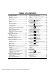
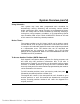
Functions Of The Keypad 1 **** **** 17 15 14 2 A B READY C D First Alert 4 OFF AWAY STAY 1 2 3 MAXIMUM TEST BYPASS 4 5 6 INSTANT CODE CHIME 7 8 9 0 # 5 16 3 ARMED 6 7 10 READY * 9 Professional SHOWN WITH FLIP-DOWN KEY COVER REMOVED 8 11 13 12 IMPORTANT!: When using the keypad to enter codes and commands, sequential key depressions must be made within 3 seconds of one another.
Functions Of The Keypad (cont’d) delay zone without causing an alarm 1. ALPHA DISPLAY WINDOW: A 2if the system is disarmed before the line, 32-character Liquid Crystal entry delay time expires. Display (LCD). Displays protection point identification and system status, 5. MAXIMUM KEY: Arms in manner messages, and user instructions. similar to AWAY mode, but 2. OFF KEY: Disarms the burglary eliminates the entry delay period, thus providing maximum protection.
Functions Of The Keypad (cont’d) 10. CHIME KEY: Turns on & off the CHIME mode. When on, any entry through a protected delay or perimeter zone while the system is disarmed will cause a tone to sound at the Keypad(s). 11. READY KEY: When depressed prior to arming the system, the keypad will display all open protection zones within the keypad's home partition. This key is also used to display all zone descriptors that have been programmed for your system, by holding the key down for at least 5 seconds. 12.
Entry/Exit Delays General Information Your system has preset time delays, known as exit delay and entry delay. Whenever you arm your system, exit delay gives you time to leave through the designated exit door without setting off an alarm. Exit delay begins immediately after entering any arming command, and applies to all modes of arming protection. If programmed, a slow beeping will sound throughout the exit delay period.
Security Codes & Authority Levels General Information At the time of installation, you were assigned an authority level and a personal four-digit security code, known only to you and yours. The security code must be entered when arming and disarming the system. The authority level defines the system functions that you can perform.
Security Codes & Authority Levels (cont’d) system. The security code must always be used to disarm the system, however. Authority Levels Authority levels define the system functions a particular user can perform. Depending on the authority assigned to you, there are certain system functions you may be prohibited from performing. In summary, there are six authority levels, each having certain system restrictions as shown below.
Security Codes & Authority Levels (cont’d) Level 7 Limited Use: Can arm and disarm the system for a predetermined number of times. Use #84 mode to set number of times. To view your authority level and system capabilities: 1. Enter your code + ✴ + ✴ . 2. The keypad will display the partition(s) that you are authorized to operate, and your user number and authority level in each partition.
Security Codes & Authority Levels (cont’d) To Exit User Edit Mode You can exit any of the user edit modes described on the following pages at any time by doing the following: 1. Press either ✴ or # , or don't press any key for 10 seconds. 2. System returns to normal mode. To Add a User IMPORTANT: Temporary users should not be shown how to use any system function they do not need to know (e.g. bypassing protection zones). CODE 1. Enter Master or Manager code and press the 8 key. 2.
Security Codes & Authority Levels (cont’d) RF BUTTON ? 0 = NO , 1 = YES This prompt will appear if a 5800 series button transmitter has been supplied and has not yet been assigned to a user. Press 1 if a button transmitter will be assigned to this user. Otherwise press 0. ENTER BUTTON ZN # (001-128) If assigning a button transmitter, this prompt will appear. Enter the button's zone number (see your installer for zone number).
Security Codes & Authority Levels (cont’d) PART. 1 A0* WHSE USER 003 AUTH=3G. When all partitions have been displayed, the keypad will scroll through the partition(s) to which access has been assigned, and will display the user number, authority level and global arm option for each. The “G” after the authority level indicates that the global arm feature is active for this user in the displayed partition. The "*" indicates the partition from which this user can be changed or deleted. The ".
Security Codes & Authority Levels (cont’d) ADD NEW USER? 0 = NO , 1 = YES The system will recognize that the user number is already in use and will prompt whether or not this is a new user. Enter 0 to change the existing user's code to the code entered in step 3. USER 002 CHANGED SUCCESSFULLY The system will confirm that the change is allowed based on authorization level, and if so, will put the new code into effect.
Accessing Other Partitions To Access Another Partition Each keypad is assigned a default partition for display purposes, and will show only that partition's information. But, if the user is authorized, a keypad in one partition can be used to perform system functions in other partitions by using the GOTO command. Note that only those partitions authorized and programmed by the installer can be accessed in this manner. To GOTO another partition: READY 1.
Accessing Other Partitions (cont’d) Master Keypad Operation A "Master" keypad is one that reflects the status of the entire system (Partitions 1-8) on its display. This is useful because it eliminates the need for a security officer in a building to have to "log-on" to various partitions from one partition's keypad to find out where an alarm has occurred.
Accessing Other Partitions (cont’d) FAULT 002 LOADING DOCK WINDOW Additional zone faults will be displayed one at a time. To display a new partition's status, press ✴ + [Partition No.]. This will display the status of the new partition. The "Armed" LED on a Master keypad will be lit only if all partitions have been armed successfully. The "Ready" LED will be lit only if all partitions are "ready to arm.
Accessing Other Partitions (cont’d) Common Lobby Operation When an installation consists of a partition that is shared by users of other partitions in a building, that shared partition may be assigned as a “common lobby” partition for the system. An example of this might be in a medical building where there are two doctors and a common entrance area. This option employs logic for automatic arming and disarming of the common lobby. Partitions may be set to affect and/or attempt to arm the common lobby.
Accessing Other Partitions (cont’d) c. Arming the last partition programmed to arm the lobby will automatically attempt to arm the lobby. If any faults exist in the lobby partition, or another partition that affects the lobby is disarmed, the lobby cannot be armed, and the message “UNABLE TO ARM LOBBY PARTITION” will be displayed.
Accessing Other Partitions (cont’d) Other Methods of Arming/Disarming When arming or disarming a partition that affects and/or arms the common lobby in one of the following manners, lobby logic remains active: • Quick-Arm • Keyswitch • Wireless Button • Wireless Keypad – 27 – Technical Manuals Online! - http://www.tech-man.
Checking For Open Zones Using the ✴ READY Key Before arming your system, all protected doors, windows and other protection zones must be closed or bypassed (see BYPASSING section). Otherwise the keypad will display a "Not Ready" message. Using the READY key will display all zones that are faulted, making it easier for you to secure any open zones. To show faulted zones: DISARMED - PRESS ✴ TO SHOW FAULTS Note: Some keypads light a green LED when the system is ready.
Displaying All Zone Descriptors Using the ✴ READY Key The Alpha Keypads can also display all the zone descriptors that are programmed in your system. The abbreviated instructions for the READY key will appear first, followed by the zone descriptors. Displaying all descriptors is useful when you need to know the zone number of a particular zone, as when bypassing zones. The "Disarmed-Ready to arm" message must be displayed before zone descriptors can be displayed.
Bypassing Protection Zones Using the 6 BYPASS Key This key is used when you want to arm your system with one or more zones intentionally unprotected. Bypassed zones are unprotected and will not cause an alarm when violated while your system is armed. All bypasses are removed when an OFF sequence (security code plus OFF) is performed. Bypasses are also removed if the arming procedure that follows the bypass command is not successful. Note: The system will not allow fire or emergency zones to be bypassed.
Bypassing Protection Zones (cont’d) Quick Bypass Your system allows you to easily bypass all open (faulted) zones without having to enter zone numbers individually. Note: All bypasses are removed when an OFF sequence (security code plus OFF) is performed. To use the Quick Bypass feature: BYPASS 1. Enter your security code and press 6 then press # . 2. BYPASS 007 FRONT UPSTAIRS BEDROOM Typical bypass message 3.
Arming Perimeter Only (With Entry Delay ON) Using the 3 STAY key Use this key when you are staying home, but might expect someone to use the entrance door later. When armed in STAY mode, the system will sound an alarm if a protected door or window is opened, but you may otherwise move freely throughout the premises. Late arrivals can enter through the entrance door without causing an alarm, but they must disarm the system within the entry delay period or an alarm will occur.
Arming Perimeter Only (With Entry Delay OFF) Using the 7 INSTANT Key Use this key when you are staying home and do not expect anyone to use the entrance door. When armed in INSTANT mode, the system will sound an alarm if a protected door or window is opened, but you may otherwise move freely throughout the premises. The alarm will also sound immediately if anyone opens the entrance door. Close all perimeter windows and doors before arming (see CHECKING FOR OPEN ZONES section). INSTANT 1.
Arming All Protection (With Entry Delay ON) Using the 2 AWAY Key Use this key when no one will be staying on the premises. When armed in AWAY mode, the system will sound an alarm if a protected door or window is opened, or if any movement is detected inside the premises. You may leave through the entrance door during the exit delay period without causing an alarm. You may also reenter through the entrance door, but must disarm the system within the entry delay period or an alarm will occur.
Arming All Protection (With Entry Delay OFF) Using the 4 MAXIMUM Key Use this key when the premises will be vacant for extended periods of time such as vacations, etc., or when no one will be moving through protected interior areas. When armed in MAXIMUM mode, the system will sound an alarm if a protected door or window is opened, or if any movement is detected inside the premises.
Disarming And Silencing Alarms Using the 1 OFF Key The OFF key is used to disarm the system and to silence alarm and trouble sounds. See "SUMMARY OF AUDIBLE NOTIFICATION" section for information which will help you to distinguish between FIRE and BURGLARY alarm sounds. IMPORTANT: If you return and the main burglary sounder is on, DO NOT enter the premises, but call the police from a nearby safe location.
Using The Keyswitch General Your system may be equipped with a keyswitch for use when arming and disarming a partition. A red and green light on the keyswitch plate indicate the status of your system as follows: Green Light: Lights when the system is disarmed and ready to be armed (no open zones). If the system is disarmed and the green light is off, it indicates the system is not ready (one or more zones are open). Red Light: Lights when system is armed or memory of alarm exists.
Chime Mode Using the 9 Key Your system can be set to alert you to the opening of a door or window while it is disarmed by using CHIME mode. When activated, three tones will sound at the Keypad whenever a protected perimeter door or window is opened, and the Not Ready message will be displayed. Pressing the READY key will display the open protection points. Note that Chime mode can be activated only when the system is disarmed. 1. To turn Chime Mode on, enter the security code and press 9 .
Viewing Central Station Messages General Information Users of the system may periodically receive messages on their display screens from their monitoring agency or installer. When a message is waiting to be viewed, the message shown below will appear. MESSAGE. PRESS 0 FOR 5 SECS. 1. Press and hold down 0 key for 5 seconds. 2. The message could take up to four screens to display all the information available. – 39 – Technical Manuals Online! - http://www.tech-man.
Panic Keys (For Manually Activating Silent And/Or Audible Alarms) Using Panic Keys Your system may have been programmed to use special key combinations to manually activate panic functions. The functions that might be programmed are Silent Emergency, Audible Emergency, Personal Emergency, and Fire. See your installer for the function(s) that may have been programmed for your system. Active Panic Functions (Your installer should note which function(s) is active in your system.
Speed Key (Macros) General Information The “A”, “B”, “C”, and/or “D” keys can be used to activate a string of commands up to 32 keystrokes each. These commands are known as a macro and are stored in the system’s memory. Typical Speed Key functions include: • Arming sequences that involve first bypassing certain zones before arming. • Seldom used but repeatable sequences. • Relay activation sequences. Defining To program a macro, enter your user code + [#] + [D].
interprets the use of the [#] key in a Speed Key sequence as its designated function only. Speed Key (Macros) (cont’d) Executing To execute a Speed Key sequence, do the following: If a lettered key, A-B-C, has been assigned as a Speed Key, press and hold down the appropriate key (about 2 seconds). If a user code is required for any part of the Speed Key sequence, the following prompt appears. Otherwise, the Speed Key sequence automatically begins. ENTER USER CODE ✴✴✴✴ Enter your user code.
Access Door Control General Information Your system may be set up such that a locked access door (such as in a lobby) can be unlocked momentarily or for a specific period of time, using a keypad command Ask your installer if this has been done in our system. Executing There are three entries that can be entered at the keypad to activate this command: 1. Enter your security code + [0]. The door will unlock for 2 seconds. 2. Enter your security code + [#] + 73, or security code + [#] + 74.
Using #70 Relay Menu Mode General Information Your system may be set up so that certain lights or other devices can be turned on or off by using the #70 command from either a keypad or a telephone keypad (if 4285 or 4286 VIP module is used). Ask your installer if this has been done in your system. To activate relays from a keypad, enter 4-digit security code + [#] +70. Follow the keypad prompts described below.
Using #70 Relay Menu Mode (cont’d) NN DEVICE IS OFF HIT THE "T" KEY Voice: "voice descriptor DEVICE nn ON/OFF. TO EXIT ENTER 00 NOW" From a keypad, press T to continue. The ENTER DEVICE NO. prompt will appear. From a telephone keypad, enter 00 to exit, or enter the next relay number to be programmed. The current on/off state of that relay will be annunciated as described above.
Using Schedules Delaying the Closing Time Your system's programmed schedules may automatically arm the system at a predetermined time. In the event a user must stay on the premises later than usual, users with master or manager authority levels can manually delay the automatic arming (closing) time up to 2 hours. To delay the closing time: 1. Enter your security code (master or manager authority levels only). 2. Press the # key, followed by 82. 3.
Using Schedules (cont’d) Schedules are comprised of an arming (closing) time window and a disarming (opening) time window. A time window is simply a defined period of time, at the end of which arming or disarming will occur. Before programming a temporary schedule, use a worksheet similar to the one below to plan your schedule. This will make it easier when actually programming the schedule.
Using Schedules (cont’d) MON DISARM WIND. 07:45AM 08:45AM The cursor will be positioned on the tens of hours digit of the start time for Monday's disarm window. Enter the desired hour. Press * to move to the minutes field. The minutes are entered in the same manner. The AM/PM indication is changed by hitting any key, 0-9, while the cursor is under the letter A/P position. Repeat for the stop time entry. Press the * key to move to the arming window for Monday.
Using Schedules (cont’d) DAYS ? MTWTFSS HIT 0-7 X X This is the prompt that actually activates the temporary schedule, and allows the temporary schedule to be customized to a particular week's needs. To select the days which are to be activated, enter the desired number 1-7 (Monday = 1). An "X" will appear under that day, indicating the previously entered schedule for that day is active. Entering a day's number again will deactivate that day. Pressing 0 will turn all days on/off.
Programming Device Timers General Information Device timers consist of an ON time & an OFF time, and selected days of the week in which they are active. There are up to 20 timers that can be used to control various devices, such as lights or appliances. Your installer will have programmed the appropriate devices into the system (up to 32 devices can be programmed). Each timer controls a single device (designated as an output number) that you select.
Programming Device Timers (cont’d) See your installer for device numbers. 00 ENTER OUTPUT# 00 Enter the desired output device number (132). As the number is entered, the device's description will appear. To delete a previously programmed timer, enter 00 as the output number. 00 ON TIME ? 00:00 PM Enter the time you want the device turned on using 00:01 - 11:59 format. When the display shows the desired time, press the * key to move to the AM/PM field. Press any key 0-9 to change the AM/PM indication.
Programming Device Timers (cont’d) 00 DAYS? MTWTFSS HIT 0-7 X X Select the days on which the device is to be activated by entering 1-7 (Monday = 1). An "X" will appear under that day, indicating the output for that day is active. Entering a day's number again will deactivate that day. Pressing 0 will turn all days on/off. The outputs will only be in effect for the days which have the letter x underneath them.
Event Log Procedures General Information To Display The Event Log The system has the ability to record various events in a history log wherein each event is recorded in one of five categories (listed below), with the time and date of its occurrence. The Event Log holds up to 224 events, with the oldest event being replaced by the logging of any new event after the log is full.
Event Logging Procedures (continued) 4. Use the [3] & [1] keys (for next and previous categories respectively) to display the categories of events. Press [8] to select a category and display the first event. Press [8] again for the next previous event. Shows burglary alarm occurred in zone 3 (C03) of partition 1 (P1), at 12:02AM on January 1.
Testing The System (To Be Conducted Weekly) Using the 5 TEST Key The TEST key puts your system into Test mode, which allows each protection point to be checked for proper operation. 1. Disarm the system and close all protected windows, doors, etc. READY should be displayed. TEST 2. Enter your security code and press the 5 key. 3. The external sounder should sound for 3 seconds and then turn off. If the sounder does not sound, it may be due to dialer communication activity. Wait a few minutes and try again.
Testing The System (cont’d) Testing Your System 1. Open and close each protected door and window in turn and listen for three beeps. The identification of each faulted protection point should appear on the display. 2. Walk in front of any interior motion detectors (if used) and listen for three beeps as movement is detected. The identification of the detector should appear on the display when it is activated. 3.
Fire Alarm System General Your fire alarm system (if installed) is on 24 hours a day, providing continuous protection. In the event of an emergency, the installed smoke and heat detectors will automatically send signals to your Control/Communicator, triggering a loud interrupting sound from the keypad. An interrupted sound will also be produced by optional exterior sounders. A FIRE message will appear at your keypad and remain on until you silence the alarm. In Case Of Fire Alarm 1.
Fire Alarm System (cont’d) 2. If the keypad does not indicate a READY condition after the second OFF sequence, press the READY key to display the zone(s) that are faulted. Be sure to check that smoke detectors are not responding to smoke or heat producing objects in their vicinity. Should this be the case, eliminate the source of heat or smoke. 3. If this does not remedy the problem, there may still be smoke in the detector. Clear it by fanning the detector for about 30 seconds. 4.
Fire Alarm System (cont’d) 2. The test may be stopped by entering any security code and pressing OFF. NOTE: The system continues to monitor all 24 hour zones (fire, panic, etc.), while this test is active, and will end the test when an alarm condition is detected. This test should be conducted at periodic intervals as determined by the local authority having jurisdiction. – 59 – Technical Manuals Online! - http://www.tech-man.
Trouble Conditions Typical Trouble Displays The word CHECK or TRBL on the Keypad's display, accompanied by a rapid "beeping" at the Keypad, indicates that there is a trouble condition in the system. To silence the beeping sound for trouble conditions, press any key. • A display of “CHECK” or “TRBL” accompanied by a display of "CALL SERVICE" indicates that a problem exists with the system that eliminates some of the protection. CALL FOR SERVICE IMMEDIATELY.
Trouble Conditions (cont’d) 970: Bell 1 Output 971: Bell 2 Output 972: Earth Ground Fault 973: J2 Trigger Output 974: Dialer 1 975: Dialer 2 988: 2nd RF Receiver – not receiving signals 990: 1st RF Receiver – not receiving signals 997: Polling Loop Short • A display of "COMM. FAILURE" at the Keypad indicates that a failure has occurred in the telephone communication portion of your system. CALL FOR SERVICE IMMEDIATELY.
Trouble Conditions (cont’d) Power Failure If the POWER indicator is off, operating power for the system has stopped and is inoperative. CALL FOR SERVICE IMMEDIATELY. If the POWER indicator is on, but the message "AC LOSS" is displayed, the Keypad is operating on battery power only. If only some lights are out on the premises, check circuit breakers and fuses and reset or replace as necessary. CALL FOR SERVICE IMMEDIATELY if AC power cannot be restored.
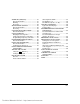
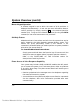
Recommendations For Proper Protection THE FOLLOWING RECOMMENDATIONS FOR THE LOCATION OF FIRE AND BURGLARY DETECTION DEVICES HELP PROVIDE PROPER COVERAGE FOR THE PROTECTED PREMISES. Recommendations For Smoke And Heat Detectors With regard to the number and placement of smoke/heat detectors, we subscribe to the recommendations contained in the National Fire Protection Association's (NFPA) Standard #72 noted below.
Recommendations For Proper Protection (cont’d) ✪ KITCHEN ▲ DINING ✪ ✪ ✪ BEDROOM BEDROOM TV ROOM ■ ✪ ✪ LIVING ROOM BEDROOM ▲ KITCHEN ✪ DINING ■ LIVING ROOM ✪ ■ ✪ BDRM BDRM ✪ BEDROOM ✪ ▲ ■ Smoke Detectors for Minimum Protection ✪ Smoke Detectors for Additional Protection ▲ Heat-Activated Detectors ■ BEDROOM ✪ ■ ✪ BEDROOM TO BR BEDROOM ■ ▲ ▲ KTCHN .
Recommendations For Proper Protection (cont’d) Recommendations For Proper Intrusion Protection For proper intrusion coverage, sensors should be located at every possible point of entry to a home or commercial premises. This would include any skylights that may be present, and the upper windows in a multi-level building.
Emergency Evacuation Establish and regularly practice a plan of escape in the event of fire. The following steps are recommended by the National Fire Protection Association: 1. Position your detector or your interior and/or exterior sounders so that they can be heard by all occupants. 2. Determine two means of escape from each room. One path of escape should lead to the door that permits normal exit from the building. The other may be a window, should your path be impassable.
Maintaining Your System Taking Care of Your System The components of your security system are designed to be as free of maintenance as possible. However, there are some things you can do to make sure that your system is in reliable working condition. 1. Test your system weekly. 2. Test the system after any alarm occurs (see TESTING THE SYSTEM).
Maintaining Your System (cont’d) Note: The low battery message comes on as a warning that battery replacement in indicated sensor(s) is due within 30 days. In the meantime, the sensor(s) causing the low battery indication is still fully operational. Important: Use only batteries recommended by your installer as replacement.
Quick Guide To System Functions FUNCTION PROCEDURE COMMENTS Check Zones Press [✱]. Display All Descriptors Arm System Press and hold [✱] for 5 seconds. Enter code. Press arming key desired(AWAY, STAY, INSTANT, MAXIMUM). Enter code. Press OFF [1]. Enter code. Press BYPASS [6]. Enter zone numbers to be bypassed (use 3-digit entries). Enter code. Press BYPASS [6]. Press [#]. Enter code. Press CHIME [9]. Enter code. Press TEST [5]. Press and hold [0] for at least 5 seconds. Enter user's code.
Quick Guide To System Functions (cont’d) FUNCTION PROCEDURE COMMENTS Change a User's Code Enter master/manager code. Press CODE [8]. Enter user's 3-digit number. Enter new code for that user. Press 0 (No) at prompt. Enter master/manager code. Press CODE [8]. Enter user no. to be deleted. Enter master/manager code. Press 1 (Yes) at prompt. Press and hold any function key for at least 5 seconds. Master & Manager level users can change their own or other users' codes.
Summary Of Audible Notification (Alpha Display Keypads) SOUND CAUSE DISPLAY LOUD, INTERRUPTED* Keypad & External LOUD, CONTINUOUS* Keypad & External ONE SHORT BEEP (not repeated) Keypad only FIRE ALARM FIRE is displayed; descriptor of zone in alarm is displayed. BURGLARY/AUDIBLE EMERGENCY ALARM ALARM is displayed; descriptor of zone in alarm is also displayed. a. SYSTEM DISARM b. SYSTEM ARMING ATTEMPT WITH AN OPEN ZONE. c. BYPASS VERIFY ONE SHORT BEEP (once every 15 sec.
Glossary The following terms are used throughout the manual. ARM/DISARM: “Armed” simply means that the burglary portion of your system is turned ON and is in a state of readiness. “Disarmed” means that the burglary system is turned OFF, and must be rearmed to become operational. However, even in a “disarmed” state, “emergency” and “fire” portions of your system are still operational. KEYPAD: This is the area on your Keypad containing numbered pushbuttons similar to those on telephones or calculators.
UL NOTICE: This is a “GRADE A” system. “FEDERAL COMMUNICATIONS COMMISSION (FCC) Part 15 STATEMENT” This equipment has been tested to FCC requirements and has been found acceptable for use. The FCC requires the following statement for your information: This equipment generates and uses radio frequency energy and if not installed and used properly, that is, in strict accordance with the manufacturer’s instructions, may cause interference to radio and television reception.
“FEDERAL COMMUNICATIONS COMMISSION (FCC) Part 68 NOTICE This equipment complies with Part 68 of the FCC rules. On the front cover of this equipment is a label that contains, among other information, the FCC registration number and ringer equivalence number (REN) for this equipment. If requested, this information must be provided to the telephone company. This equipment uses the following jacks: An RJ31X is used to connect this equipment to the telephone network.
CANADIAN DEPARTMENT OF COMMUNICATIONS (DOC) STATEMENT NOTICE The Canadian Department of Communications label identifies certified equipment. This certification means that the equipment meets certain telecommunications network protective, operational and safety requirements. The Department does not guarantee the equipment will operate to the user’s satisfaction.
WARNING! THE LIMITATIONS OF THIS ALARM SYSTEM While this system is an advanced design security system, it does not offer guaranteed protection against burglary or fire or other emergency. Any alarm system, whether commercial or residential, is subject to compromise or failure to warn for a variety of reasons. For example: • Intruders may gain access through unprotected openings or have the technical sophistication to bypass an alarm sensor or disconnect an alarm warning device. • Intrusion detectors (e.g.
WARNING! THE LIMITATIONS OF THIS ALARM SYSTEM (continued) • Alarm warning devices such as sirens, bells or horns may not alert people or wake up sleepers if they are located on the other side of closed or partly open doors. If warning devices sound on a different level of the residence from the bedrooms, then they are less likely to waken or alert people inside the bedrooms.
Index #70 command ........................................ 44 4285 or 4286 VIP module ................. 8, 44 AC Loss.................................................. 62 Access Another Partition...................... 22 Access Door ........................................... 43 Add a User............................................. 18 ADD NEW USER.................................. 20 Add User Code ...................................... 17 First Alert Dealer ................................. 62 Alarm......
Low Battery...........................................67 Low Battery Warning ...........................68 LSENS ...................................................61 macro .....................................................41 Macros......................................................6 Manager.................................................16 Master....................................................16 Master Keypad ..................................8, 23 Maximum .......................................
LIMITED WARRANTY Pittway Corporation, and its divisions, subsidiaries and affiliates ("Seller"), 165 Eileen Way, Syosset, New York 11791, warrants its First Alert products to be in conformance with its own plans and specifications and to be free from defects in materials and workmanship under normal use and service for 36 months from the date stamp control on the product or, for products not having a date stamp, for 30 months from date of original purchase unless the installation instructions or catalog set